Audio Enhancement WV-SF448 User Manual
Page 26
26
IMPORTANT:
• Do not connect 2 wires or more directly to a terminal. When it is necessary to connect 2
wires or more, split the wire and connect the split wires to the terminal.
• Input and output of the External I/O terminal 2 and 3 can be switched by configuring the set-
ting. “Off” is selected by default. It is possible to determine whether or not to receive input
from External I/O terminal 2 and 3 (ALARM IN2, 3) by selecting “Off”, “Alarm input”, “Alarm
output” or “AUX output” for “Terminal 2” or “Terminal 3” on the [Alarm] tab of the “Alarm”
page. Refer to the Operating Instructions on the provided CD-ROM for further information.
• Connect an external device with verifying that the ratings are within the specifications below.
• When using the External I/O terminals as the output terminals, ensure they do not cause
signal collision with external signals.
• In order for the External I/O terminal to detect alarm inputs when the terminal status is
changed from Open to Close (On) or from Close to Open (Off), about 100 ms or more is
needed. Because alarms cannot be detected for about 5 seconds after a detection is made,
alarm inputs received within about 5 seconds after an alarm is detected are not detected.
• ALARM OUT, AUX OUT
Output specification: Open collector output (maximum applied voltage: 20 V DC)
Open: 4 V - 5 V DC by internal pull-up
Close: Output voltage 1 V DC or less (50 mA or less)
• ALARM IN
Input specification: No-voltage make contact input (4 V - 5 V DC, internally pulled up)
Off: Open or 4 V - 5 V DC
On: Make contact with GND (required drive current: 1 mA or more)
b
Connect a LAN cable (category 5 or better, straight,
STP*) to the network connector.
* E model only
n
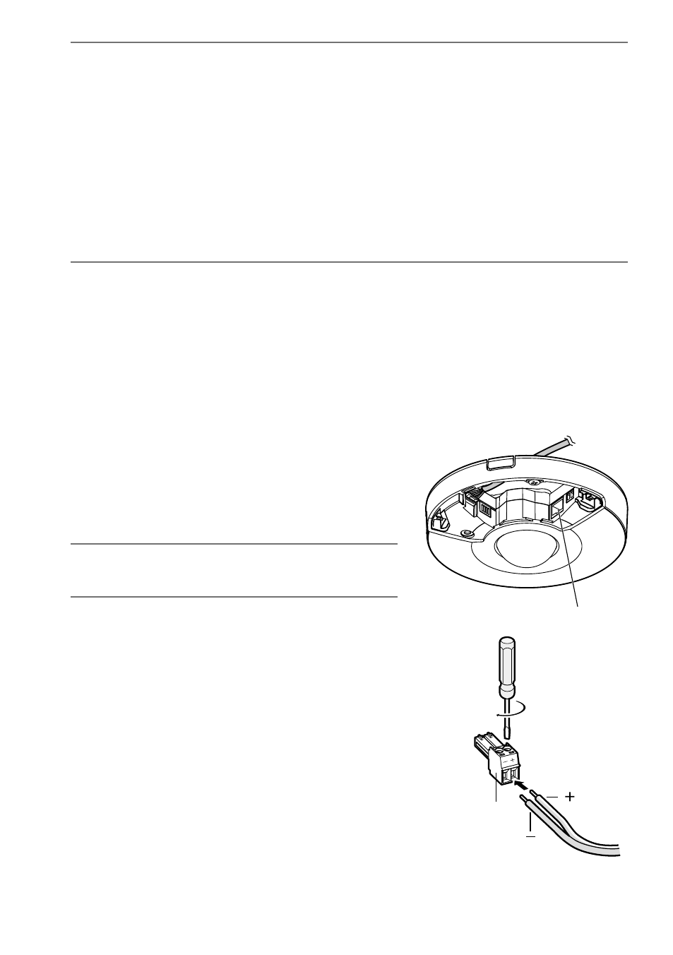
Connect the power supply.
IMPORTANT:
• The 12 V DC power supply shall be insulated from
the commercial AC power.
When using 12 V DC power supply*
q Loosen the screws of the power cord plug (accessory).
w Connect the cable of the 12 V DC power supply* to the
power cord plug.
Strip 3 mm - 7 mm {1/8 inches - 9/32 inches} from the
end of the wire, and twist the stripped part of the wire
sufficiently to avoid short circuit.
Specification of cable (wire):
16 AWG - 24 AWG, Single core, twisted
• Check whether the stripped part of the wire is not
exposed and is securely connected.
e Tighten the screws of the power cord plug.
(Recommended tightening torque:
0.34 N·m {0.25 lbf·ft})
r Connect the power cord plug to the 12 V DC power
supply terminal.
* ONLY CONNECT 12 V DC CLASS 2 POWER SUPPLY
or LIMITED POWER SOURCE.
Network connector
(12 V DC)
(GND)
12 V DC power
cord plug
(accessory)