Connection – Audio Enhancement WV-SF448 User Manual
Page 23
23
Connection
Before starting the connection, turn off the power of this camera and the devices to be connected.
Check and prepare the required devices and cables for connection.
Note:
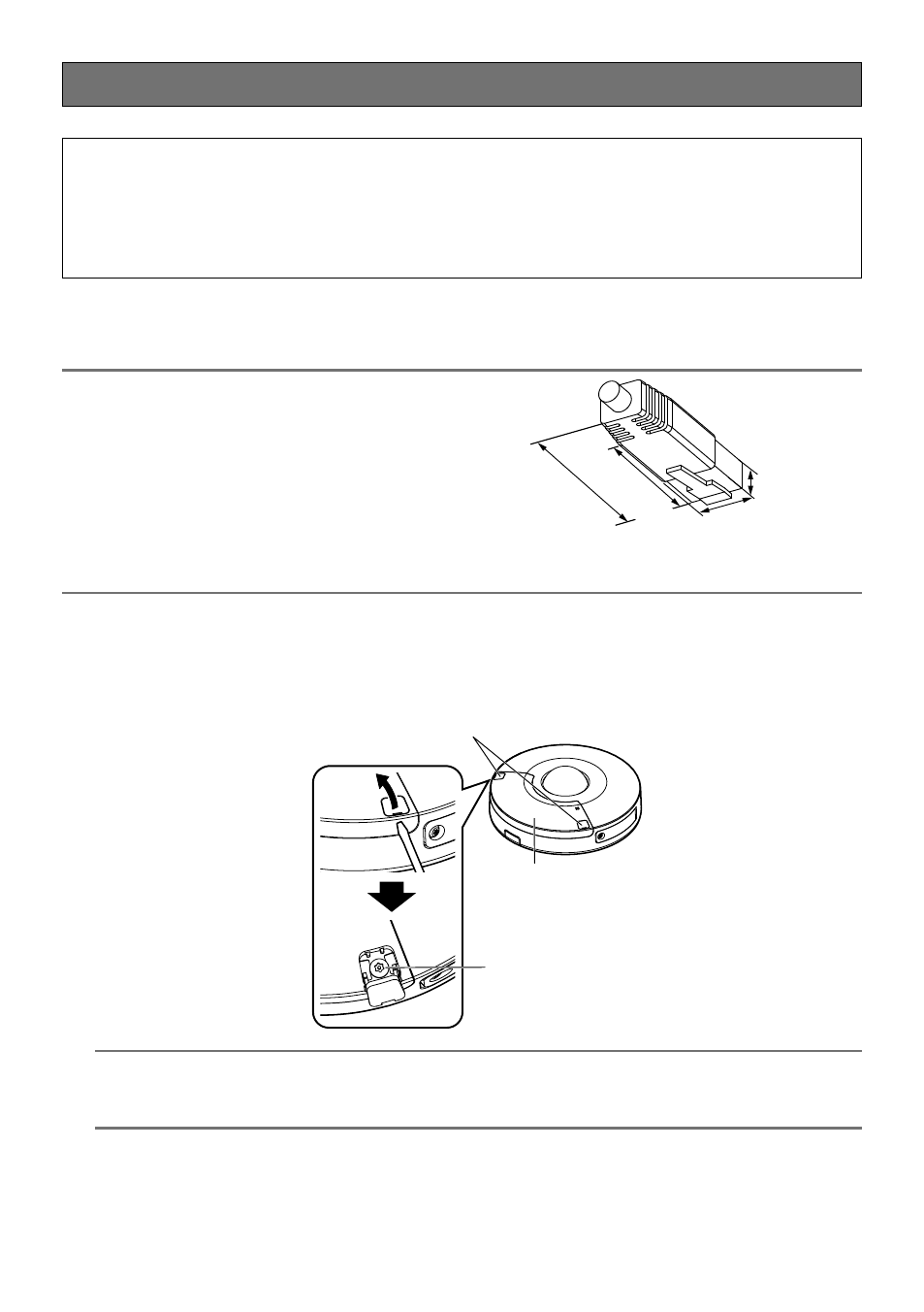
• Since the connector storage section does not
have a sufficient space, use a LAN cable that do
not exceed the sizes described in the illustrations.
40 mm {1-9/16 inches}
Straight section
30 mm {1-3/16 inches}
9 mm
{11/32 inches}
13 mm {1/2 inches}
Example of LAN cable connector
Caution:
• ONLY CONNECT 12 V DC CLASS 2 POWER SUPPLY (UL 1310/CSA 223) or LIMITED
POWER SOURCE (IEC/EN/UL/CSA 60950-1).
• A READILY ACCESSIBLE DISCONNECT DEVICE SHALL BE INCORPORATED TO THE
EQUIPMENT POWERED BY 12 V DC POWER SUPPLY.
z
Remove the sub cover.
Open the screw covers x2 of the camera with a thin tool* as illustrated. Loosen the sub cover
fixing screws x2 using the bit for tamperproof screw (accessory), then remove the sub cover.
* A slotted head screwdriver etc.
IMPORTANT:
• Do not use excessive force when removing the sub cover. Failure to observe this may dam-
age the sub cover.
Screw covers
Sub cover
Sub cover
fixing screw