9 specifications, Table 1-5, Transition module cables – Artesyn MVME7616E Transition Module Installation and Use (April 2015) User Manual
Page 19: Table 1-6, Mvme761-0x1 specifications, General information
General Information
MVME7616E Transition Module Installation and Use (6806800A43D)
19
1.9
Specifications
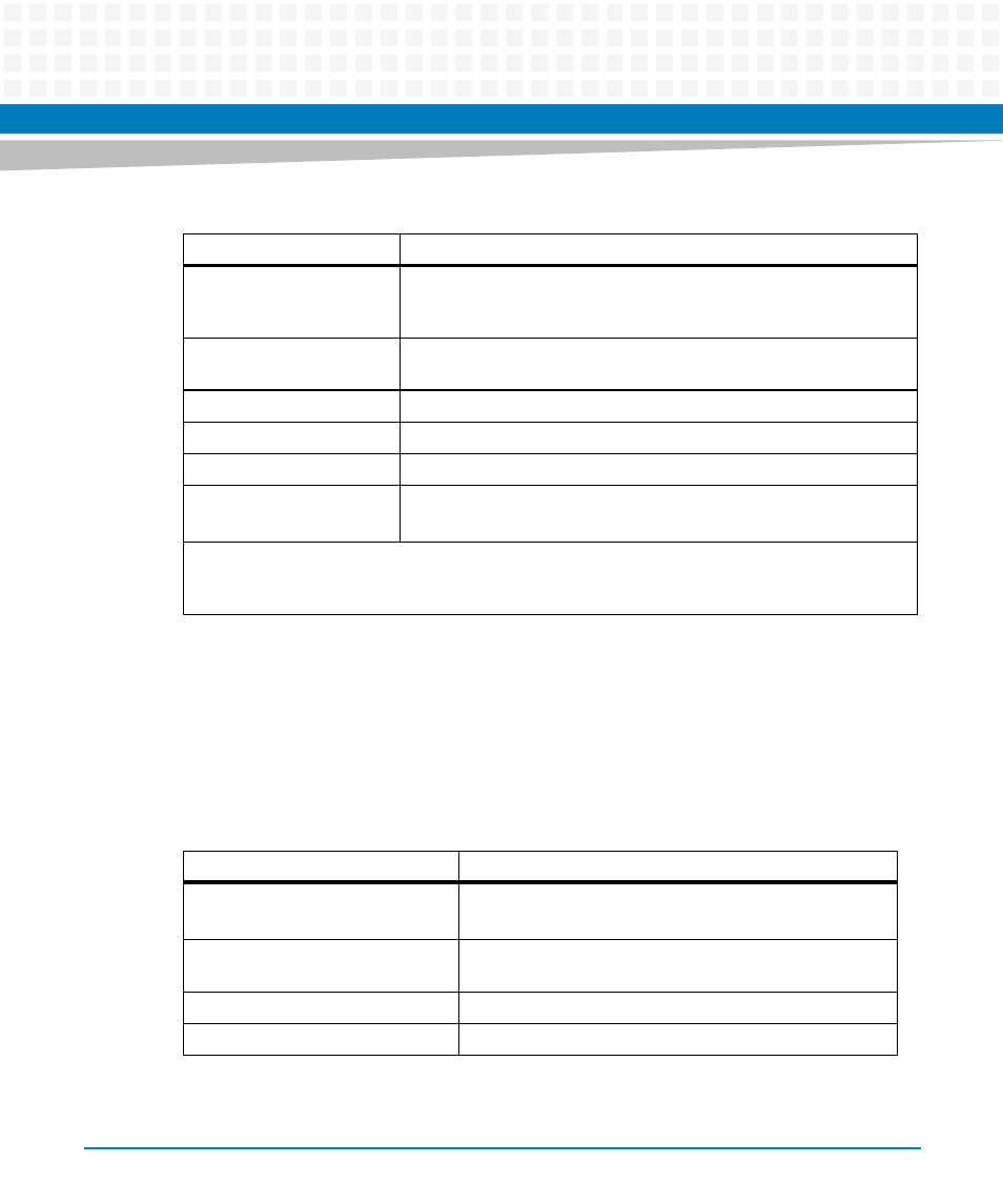
The MVME761 transition module specifications are shown in the next table.
Table 1-5 Transition Module Cables
Part Number
Description
Included with the
MVME761-0x1
64-line flat ribbon cable with 96-pin DIN connectors that connects P2
on the MVME761transition module to J3 on the 3-row P2 Adapter or J4
on the 5-row P2 adapter; 13 inches long. (30-W2799B02A).
User-supplied
EIA-232-D DTE or DCE cable (pins used depend on the processor
VMEmodule)
User-supplied
Centronics- type parallel printer cable, male-to-male
User-supplied 20-conductor
cable; usually supplied with the modem
User-supplied 6-conductor
cable; usually supplied with the modem
CBL761HD26DB25
Straight-through adapter cable with male HD-26 connector and female
DB-25 connector, 3 feet long. (30-NW9302B27)
If you supply your own 64-line cable to connect the P2 adapter to the MVME761 transition module, the
cable should not be longer than 1.5 feet. A longer cable is likely to cause problems, especially for the
Ethernet and parallel port signals.
Table 1-6 MVME761-0x1 Specifications
Characteristics
Specifications
Power Requirements
+12 Vdc, 100 mA typical, 200 mA maximum
-12 Vdc, 100 mA (for some of the SIMs)
Operating temperature
0
o
to 55
o
C at chassis point of entry of forced air
(approximately 5 CFM)
Storage temperature
-40
o
to +85
o
C
Relative Humidity
5% to 90% (non-condensing)