10 gpio, Table 4-1, Gpio description – Artesyn COMX-P2020 Installation and Use (July 2014) User Manual
Page 83: Functional description
Functional Description
COMX-P2020 COM Express Module Installation and Use (6806800K97D)
83
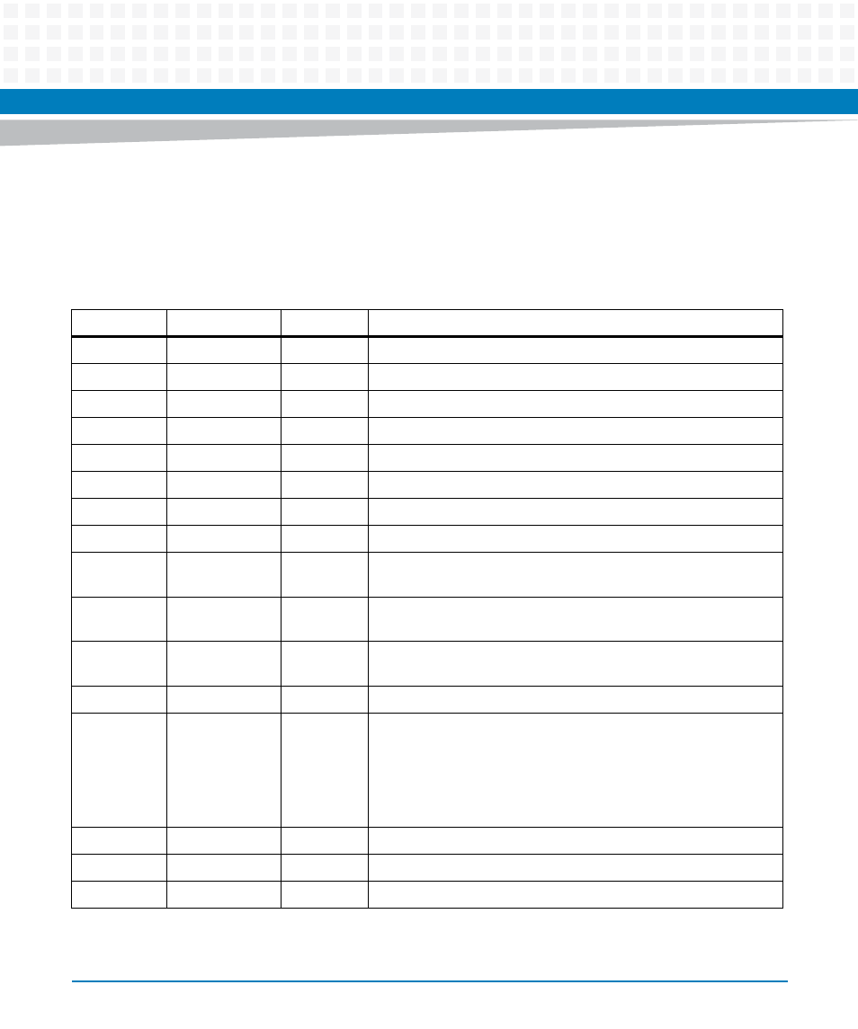
4.10 GPIO
There are total 14 GPIO PIN used at COMX-P2020; GPIO8 and GPIO9 are used for SDHC
function.
Table 4-1 GPIO Description
Name
Intput/ Output
Reset Value Description
GPIO 0
Input
connected to the COM-E carrier board
GPIO 1
Input
connected to the COM-E carrier board
GPIO 2
Input
connected to the COM-E carrier board
GPIO 3
Input
connected to the COM-E carrier board
GPIO 4
Output
0
connected to the COM-E carrier board
GPIO 5
Output
0
connected to the COM-E carrier board
GPIO 6
Output
0
connected to the COM-E carrier board
GPIO 7
Output
0
connected to the COM-E carrier board
GPIO 8
Multiplex as SDHC_CD: which is used to check if the SD insert or
not.
GPIO 9
Multiplex as SDHC_WP: which is used to check the SD is write
protect or not.
GPIO 10
Output
0
can be used to clear WDT timer.
If the pin is set to 1, the WDT timer will be cleared.
GPIO 11
Input
connected to the COM-E carrier board
GPIO 12
Output
1
If this pin is set to 1, and s3[14] is set to OFF, then Serdes#2 is
switch to COMe PCI #2;
If this pin is set to 0, or s3[14] is set to ON, then Serdes#2 is switch
to GEPHY2.
For COMX-P2020, GPIO[12] must be set to 1 and s3[14] must be
set to OFF.
GPIO 13
Input
connected to the COM-E carrier board
GPIO 14
Input
connected to the COM-E carrier board
GPIO 15
Input
connected to the COM-E carrier board