Controls, indicators and connectors, 1 face plate, 1 leds – Artesyn Centellis 2000 User Card-10GE with Telco Alarm Installation and Use (May 2014) User Manual
Page 33: Table 3-1, Face plate leds, Figure 3-1, Face plate, Chapter 3
Chapter 3
Centellis 2000 User Card 10GE with Telco Alarm Installation and Use (6806800M46B)
33
Controls, Indicators and Connectors
3.1
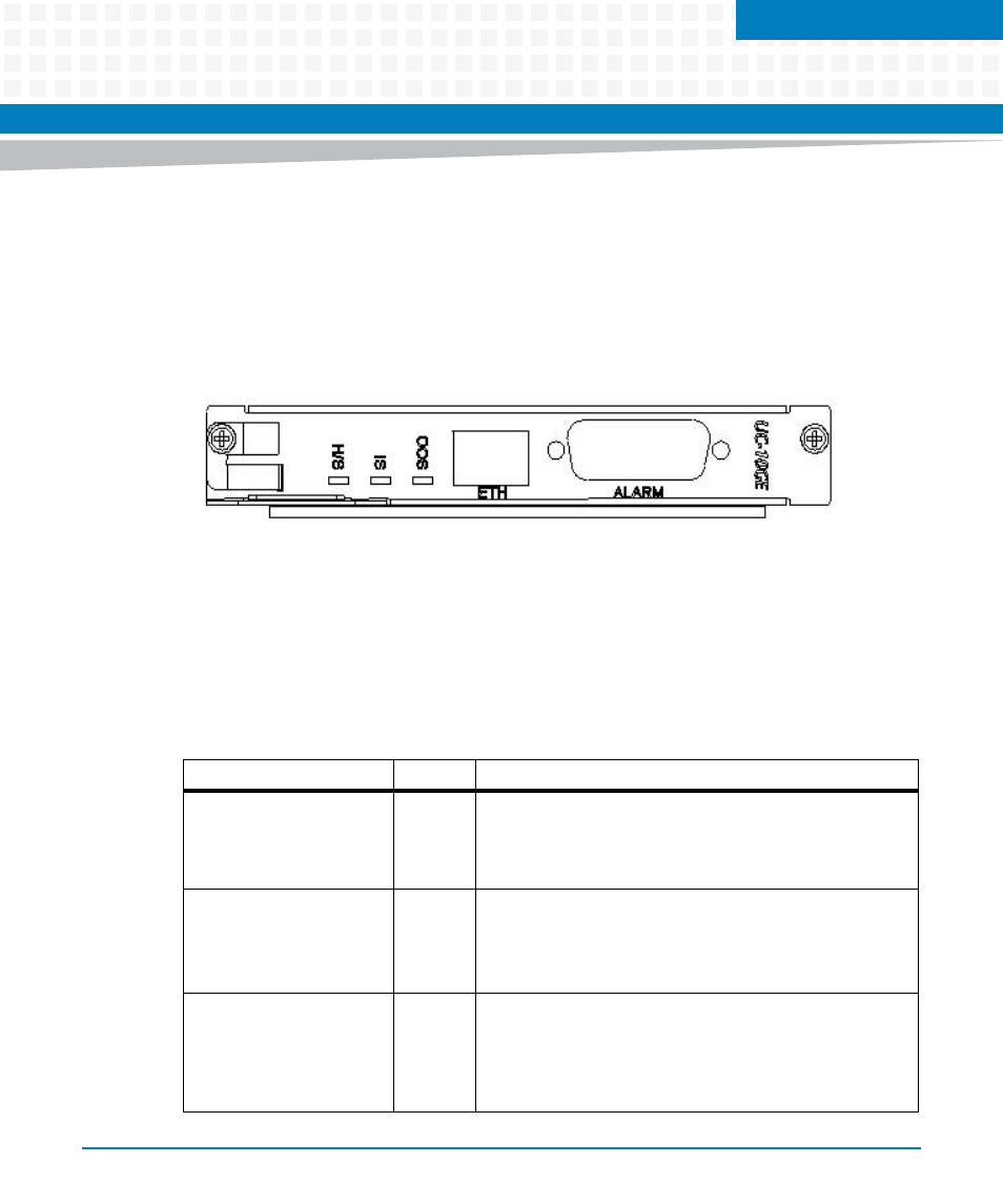
Face Plate
The following figure highlights the position of LEDs and connectors on the face plate of the
board. The LEDs and connectors are described in sections
3.1.1
LEDs
The following LEDs can be found on the face plate of the board. OOS, OK and H/S are ATCA LEDs
and can be controlled via IPMI. For more information, refer Centellis 2000 User Card 10GE with
Telco Alarm: Control via IPMI Programmer’s Reference manual.
Figure 3-1
Face Plate
Table 3-1 Face Plate LEDs
LED
Color
Description
OOS (failure)
Red
Red: The Centellis 2000 User Card 10GE with Telco Alarm is
out-of-service.
Off: The Centellis 2000 User Card 10GE with Telco Alarm is
working properly.
OK (power)
Green
Green: The Centellis 2000 User Card 10GE with Telco Alarm
is operating properly.
Off: Otherwise
Blinking: The board boots up.
H/S
Blue
Blue: The Centellis 2000 User Card 10GE with Telco Alarm is
ready to be extracted.
Off: The Centellis 2000 User Card 10GE with Telco Alarm is
not ready to be extracted. Do not remove the board during
this state.