Aplex Technology ACS-2685 User Manual
Page 34
ACS-2685 User Manual
34
MODEL
SATA Color
RAID
ASB-M801B
Black:
SATA1/SATA2/SATA3/SATA4
No
ASB-M801EB
Blue: SATA1/SATA2/SATA3
Black: SATA4
Yes
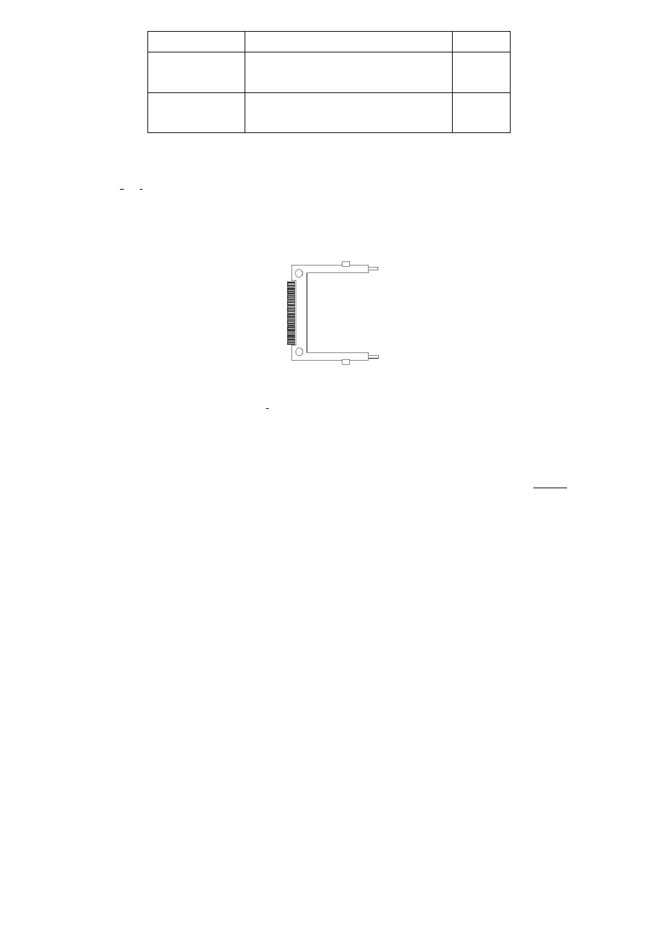
36. IDE_CF1
(Option):
(CF
Card socket), it is located at the bottom of the board and serves as an insert
interface for Type I and Type II Compact Flash card. The operating voltage of CF card
can be set as 3.3V or 5V,The default setting of the product is 3.3V. Please refer to
description of JCF/JSATA Jumper setting.
37. CPU SCREW HOLES:
CPU FAN SCREW HOLES,
Four screw holes for fixed CPU Cooler assemble.
38. H5/H6:
MPCIE1 SCREW HOLES, H5 for
mini PCIE card (30mmx30mm) assemble.
H6 for
mini PCIE
card (30mmx50.95mm) assemble.
39. LED1:
LED STATUS. Green LED for Motherboard Standby Power Good status, Yellow LED for
HDD status.