Aplex Technology ACS-2685 User Manual
Page 30
ACS-2685 User Manual
30
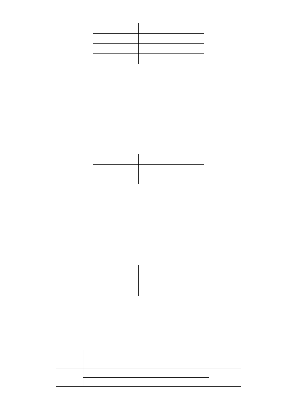
JP_104P Pin#
PC104+ VIO Voltage
All Open
Default
Close 1-2
+3.3V PCI Card
Close 2-3
+5V PCI Card
27. PC104+ (option):
(4x30 Pin),
PC104 plus type connector. Can expand support four PCI devices.
ASB-M801B/EB:PC104+ type connector in the Bottom.
28. PCIEX2 (option):
(4x10 Pin), PCIe bus connector, it conforms to standard PCI Express x1 specification.
Can expand support PCIe devices.
ASB-M801B/EB:PCIEX2 connector in the Bottom.
MODEL
PC104+ / PCIEX2
ASB-M801B
Bottom
ASB-M801EB
Bottom
29. MPCIE1:
(Socket 52Pin),mini PCIe socket, it is located at the top, it supports mini PCIe devices
with USB2.0, SMBUS and PCIe signal. MPCIe card size is 30x30mm or 30x50.95mm.
30. JRI:
(2.0mm Pitch 1X3 Pin Header), Wake up setting jumper. pin 1~2 are used to select
signal for COM4 Wake up, pin 2~3 are used to select signal for PCI devices Wake up,
JRI Pin#
Function
Close 1-2
PCI_PME for COM4
Close 2-3
PCI-PME for PCI
31. MIO1:
(1.25mm Pitch 2x20 Connector),For expand output connector, It provides two RS232
ports or one RS485 port, three USB ports, one power led, one power button, via a
dedicated cable connected to TB-523 MIO1.
Functio
n
Signal Name
Pin# Pin#
Signal Name
Function
422RX+
1
2
485+ / 422TX+
COM3
422RX-
3
4
485- / 422TX-