Aplex Technology ARCHMI-716 User Manual
Page 52
ARCHMI-7XX (SBC-7106A) User Manual
51
3
TXD (Transmit Data)
4
DTR (Data Terminal Ready)
5
Ground
6
DSR (Data Set Ready)
7
RTS (Request To Send)
8
CTS (Clear To Send)
9
JP6 Setting:
Pin1-2 : RI (Ring Indicator) (default)
Pin3-4 : 5V Standby power (option)
Pin5-6:12V Standby power (option)
S1:
PWR BT: POWER on/off Button, They are used to connect power switch button.
The two pins are disconnected under normal condition. You may short them
temporarily to realize system startup & shutdown or awaken the system from
sleep state.
PWR LED: POWER LED status.
S1
Model
Yes
TB-528C1U2P1
No
TB-528C1U2
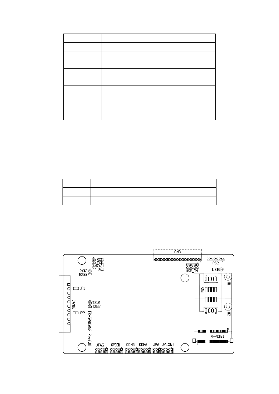
41. TB-528CAN2 R0.10 (option):
SBC-7106A Riser Card,TB-528CAN2 CN3 connect to SBC-7106A CN3 pin Header.
It provides two CAN-bus Interface.
TB-528CAN2 Top: