Connecting the usb smartcable – Zilog ZMOT0BHH User Manual
Page 19
UM023902-1013
15
ZMOTION
®
20-Pin Detection and Control Development Kit
User Manual
4. Use the provided ⅜" machine screws (4) with a nut to secure the lens holder in place;
see the example in
Connecting the USB SmartCable
Observe the following steps to connect the USB SmartCable to the ZMOTION 20-Pin
Development Board.
The power to the development board must be disconnected or turned OFF before con-
necting or disconnecting the USB SmartCable.
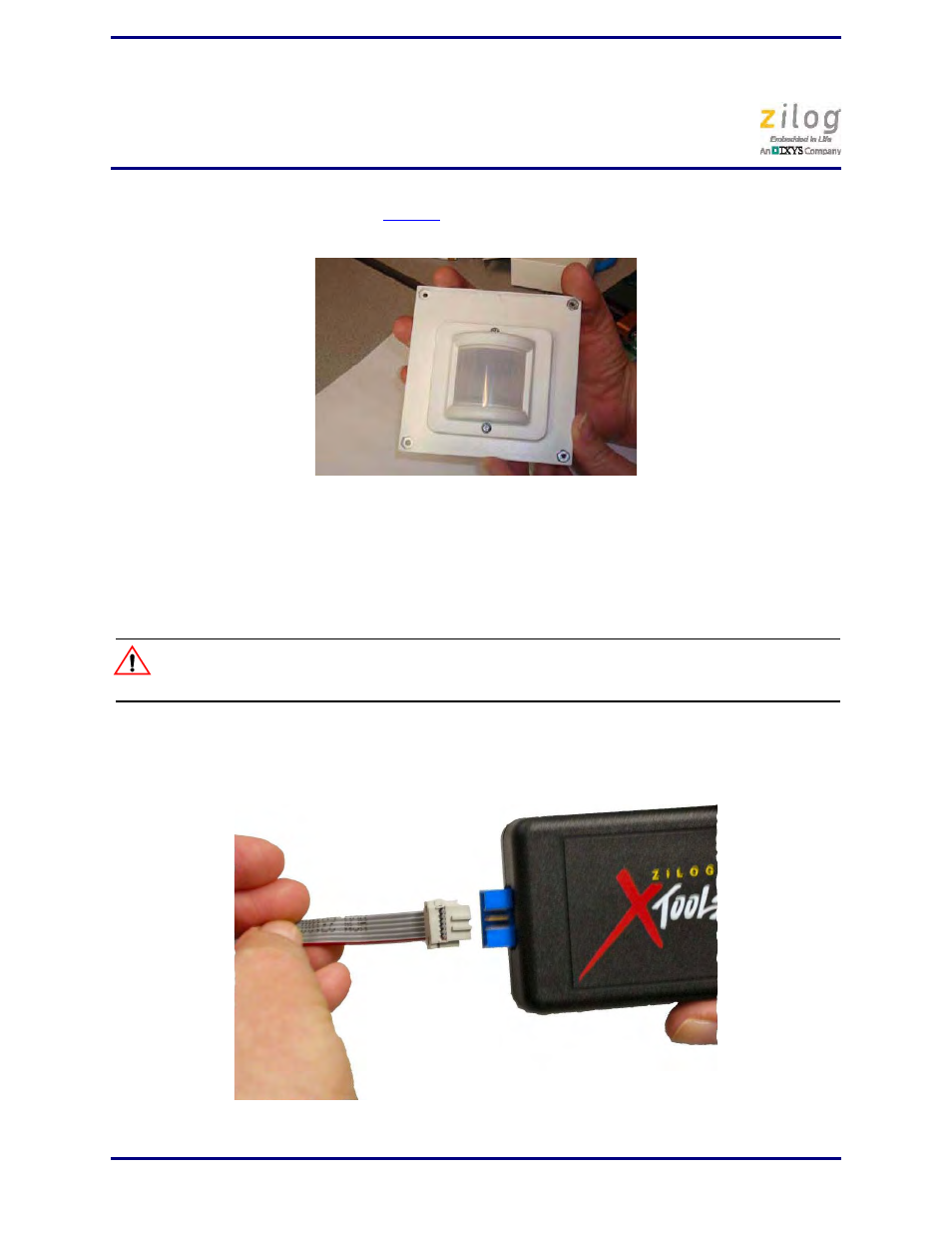
1. Attach one end of the six-conductor ribbon cable (included) to the USB SmartCable
six-pin DBG connector, as shown in Figure 11.
Figure 10. Assembled Flat 0.9" Lens Holder and Flat Lens
Figure 11. Connecting the Six-Conductor Ribbon Cable to the USB SmartCable
Caution: