Ez80f92 development kit user manual – Zilog eZ80F92 User Manual
Page 21
eZ80F92 Development Kit
User Manual
UM013911-0607
Operational Description
17
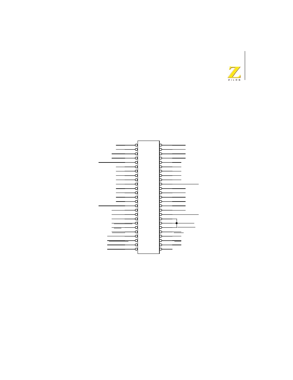
I/O Connector
Figure 7 illustrates the pin layout of the I/O Connector in the 50-pin
header, located at position JP2 on the eZ80Acclaim!
®
Development Plat-
form. Table 3 describes the pins and their functions.
Figure 7. eZ80Acclaim!
®
Development Platform
I/O Connector Pin Configuration—JP2
PB1
PB3
PB5
PB7
PC1
PC3
PC5
PC7
GND_EXT
PD1
PD3
PD5
PD7
DIS_IRDA
CS3
EZ80CLK
V3.3_EXT
FLASHWE
NMI
WAIT
GND_EXT
PB0
PB2
PB4
PB6
GND_EXT
PC2
PC4
RTC_VDD
PD0
PD2
PD4
PD6
GND_EXT
IICSCL
IICSDA
TDI
TDO
TRIGOUT
TCK
TMS
RESET
GND_EXT
HALT_SLP
V3.3_EXT
PC6
PC0
JP2
HEADER 25X2
IDC50
1
2
3
4
5
6
7
8
9
10
11
12
13
14
15
16
17
18
19
20
21
22
23
24
25
26
27
28
29
30
31
32
33
34
35
36
37
38
39
40
41
42
43
44
45
46
47
48
49
50
See also other documents in the category Zilog Sensors:
- S3F94C8 (11 pages)
- S3F80QB (29 pages)
- S3F8S19 (38 pages)
- Z51F6412 (96 pages)
- Z51F6412 (54 pages)
- Z51F6412 (55 pages)
- Z16F6411 (216 pages)
- EZ80F93 (11 pages)
- Z16F6411 (20 pages)
- ZMOT0BSB (314 pages)
- ZMOT0BSB (582 pages)
- EZ80F93 (13 pages)
- Z8F083A (14 pages)
- Z8F082A (18 pages)
- Z8F2480 (17 pages)
- Z8F082A (15 pages)
- Z8F0822 (17 pages)
- Z8F6423 (83 pages)
- Z8F2480 (19 pages)
- Z8F2480 (18 pages)
- Z8F6423 (18 pages)
- Z8F6423 (27 pages)
- Z8F6482 (50 pages)
- EZ80F91GA (469 pages)
- EZ80F915 (411 pages)
- EZ80F91NAA (34 pages)
- EZ80F91 (41 pages)
- EZ80L92 (40 pages)
- EZ80L92 (26 pages)
- EZ80L92 (79 pages)
- EZ80L92 (10 pages)
- ZUSBOPTS (59 pages)
- Z16FMC6 (520 pages)
- Z8FMC16 (26 pages)
- Z16FMC6 (41 pages)
- ZUSBOPTS (38 pages)
- Z16FMC6 (8 pages)
- Z16FMC6 (26 pages)
- ZMOT1AHH (25 pages)
- ZMOT0BSB (34 pages)
- EZ80F915 (78 pages)
- EZ80190 (87 pages)
- EZ80L92 (86 pages)
- EZ80F91GA (127 pages)