Venting installation – Desa CB36N User Manual
Page 11
www.desatech.com
117437-01D
11
VENTING INSTALLATION
Continued
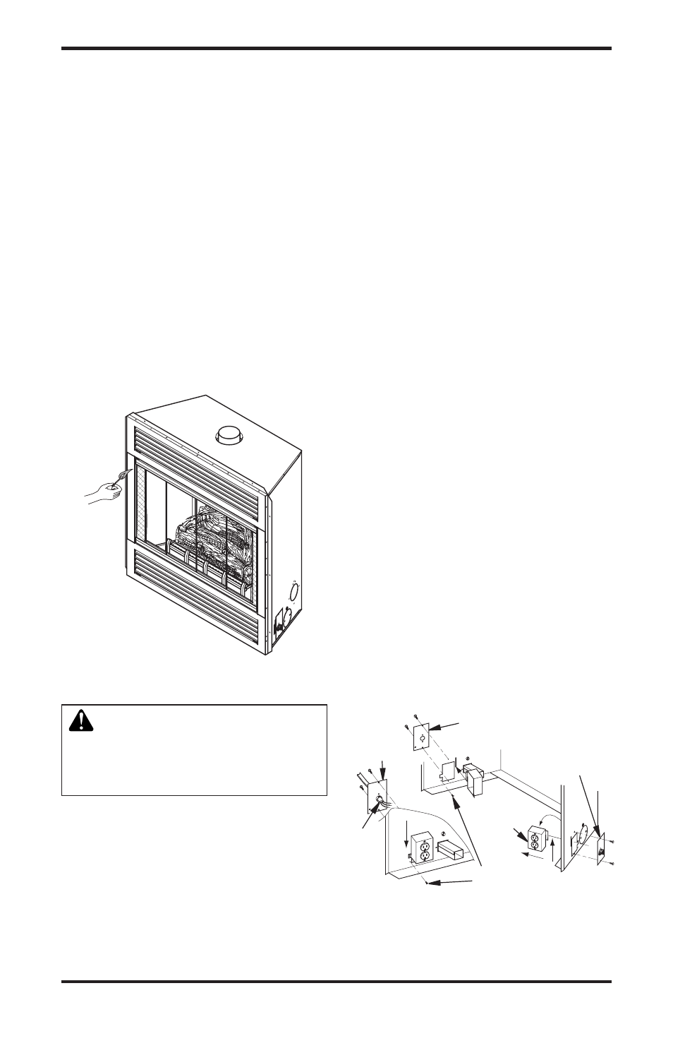
CHECKING FOR PROPER VENTING
After completing and checking electrical,
gas and vent connections, follow lighting
instructions.and.allow.main.burner.to.run.for.
approximately. 5. minutes.. Hold. a. match. or.
butane lighter flame, near opening between
glass and fireplace face and play it along
entire.length.of.opening.(Smoke.may.also.be.
used). Proper venting will tend to draw flame
or smoke into appliance. Improper venting,
escaping or spillage of burned gas, is indi-
cated when match flickers or goes out (see
Figure.1)..Smoke.will.also.tend.to.disperse.
away.from.appliance.
If appliance is not venting properly, shut it off
and notify your installer or a qualified service
agency.to.inspect.venting.system.
Figure 12 - Checking for Spillage
Figure 13 - Relocating Junction Box Recep-
tacle and Electrical Supply Connection
ELECTRICAL SUPPLY CONNECTION
CAUTION: Disconnect the
electrical power to the supply
circuit before attempting to con-
nect or service this appliance.
A prewired junction box receptacle with strain
relief.is.provided.on.right.side.of.cabinet.for.
hard wiring unit to a 15 Amp, 120 VAC, 60 Hz
grounded.branch.circuit..If.installation.demands.
electrical supply be connected from the left, the
entire.receptacle.box.can.be.relocated.to.the.
left.side.by.following.these.instructions:
J-Box.
Cover.
with.Strain.
Relilef
J-Box.
Cover
Romex.
Cable
J-Box.with.
Receptacle
J-Box.Cover.
with.Strain.
Relief
Screw/Tab.
Retainer
Note: If you do not need to relocate the junc-
tion box, to connect the electric supply follow
steps 8 through 11 only:
1.. Remove..screws.and.outer.cover.with.
strain.relief.bushing.on.right.side.of.cabi-
net.(see.Figure.13).
2. Remove inner retaining screw on junction
box.mounting.tab.
3. Slide junction box up until screw mounting
tab.is.lined.up.to.notch.in.outer.cabinet.
4. Swing junction box out and slip retaining
flange out through slot in outer cabinet.
5.. Remove..screws.and.outer.cover.on.left.
side.of.outer.cabinet.
6. Reinsert junction box retaining flange
through.slot.now.on.left.side.and.swing.
screw.mounting.tab.back.through.notch.
as.before.
7. Slide junction box down till mounting tab
holes.line.up.and.replace.inner.retaining.
screw.
8. With junction box cover removed, pull
end.of.3-wire.Romex.supply.line.through.
universal. strain. relief. bushing. on. cover..
(see.Figure.13).
9.. Strip.back.outer.Romex.to.about.4".and.
connect black, white and green wires ac-
cordingly.using.3.wire.nut.connectors.
10. Tuck tailing wires into junction box and
replace junction box cover using 2 remain-
ing.screws.
11. Tighten adjustment on universal strain
bushing.to.secure.Romex.sheathing.and.
complete.supply.connection.