Fuel pump fmu assembly, 1 fuel pump fmu assembly i, Fuel pump fmu assembly -1 9.1 – Paxton Superchargers Dodge SRT-10 Ram User Manual
Page 31: Fuel pump fmu assembly installation -1, 1 fuel pump fmu assembly installation
9-1
P/N: 4809645
©2006 Paxton Automotive
All Rights Reserved, Intl. Copr. Secured
16JAN06 v1.2 SRT-10(4809645v1.2)
Section 9
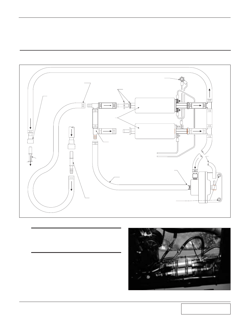
FUEL PUMP FMU ASSEMBLY
9.1 FUEL PUMP FMU ASSEMBLY
INSTALLATION
+
+
_
_
ROUTE TO CHASSIS GROUND LOCATION
ROUTE TO TEE
IN BYPASS
VALVE VACUUM
LINE
MARK AND DRILL TWO HOLES.
INSTALL THE SUPPLIED SHETT METAL
SCREWS TO HOLD THE FUEL CONTROL UNIT
SUPPLIED
FUEL PUMPS
SUPPLIED FEMALE
SPRING LOCK
CONNECTOR
VEHICLE
FUEL RAIL
SUPPLIED FEMALE
SPRING LOCK
CONNECTOR
INSTALL AND TIGHTEN CLAMP
USING STEPLESS CLAMP PLIERS
(20 PLACES)
VEHICLE SUPPLY
LINE FROM FUEL
TANK
SUPPLIED FUEL PUMP FITTINGS (4 PLACES)
(VERIFY THAT THE COPPER WASHER IS
INSTALLED AND FITTING IS TIGHT)
5/32" HOSE (CONNECTED
TO MANIFOLD PRESSURE)
5/16" HOSE BARB
TEE (4 PLACES)
CUT SUPPLIED EFI FUEL
HOSE TO LENGTH (10
PLACES)
RED WIRES WITH STRIPE
(FROM IGNITION TIMING
CONTROL BOX)
Fig. 9-a
Fig. 9-b
A.
Plumb the supplied fuel pumps in parallel by
connecting the pump outlets. The pumps are
now configured so that one TEE feeds both
pump inlets and another TEE draws from
both pump outlets. In back of the manual
(See Appendix A-3) as a reference to assem-
ble the pump assembly.
*** NOTE ***
Because of the close proximity to the exhaust system,
the fuel lines need to be shielded. Install the supplied
heat resistant covering to all of the fuel lines leading to
the fuel management unit and the feed and supply
lines.