Block diagram, Intel bay trail soc – NEXCOM NEX 617 User Manual
Page 38
Copyright © 2014 NEXCOM International Co., Ltd. All Rights Reserved.
24
NEX 617 User Manual
Chapter 2: Jumpers and Connectors
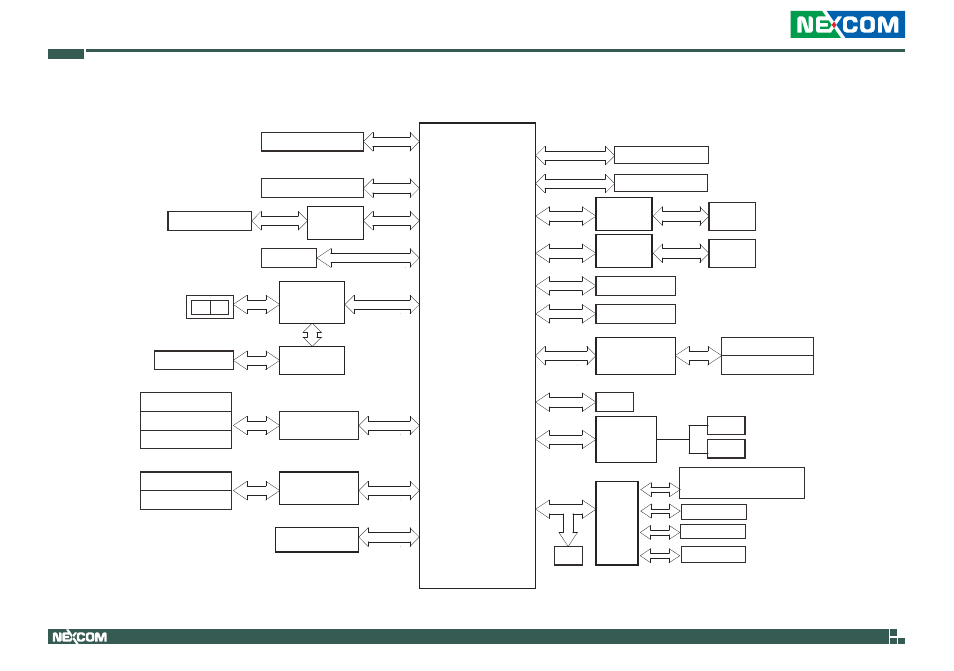
Block Diagram
Gb LAN
RJ45 #1
SATAII Bus
(Shared)
HDMI
DDI Port 0
SPI FLASH
SATAII Bus
1.8V/64Mb
RTL8111G-CG
Realtek
Realtek
ASM1074
DDI Port 1
Chrontel
USB 3.0 Hub
NCT6106
DDR3L 1333/1066
Audio Amplifier
Audio Codec
ALC662
ALC109-CG
MIC
Line
Out
TPM
5Gbps
2 Front USB3.0 ports
2 Rear USB3.0 ports
ANALOG PORT
480Mbps
3 ports
High-Speed USB
USB 3.0 Hub
Asmedia
LPC
Intel
Bay Trail SoC
VRD on Board
SPI
SATA2_1
2 Rear USB2.0 ports
Realtek
FCBGA 1170
Channel B
CH7511B
SIO
Nuvoton
LVDS (header)
LVDS
24MHz
128-bit Dual-Channel Memory x 2 Slots
DDR3L 1333/1066
Channel A
Serial Port * 5
- Rear IO *3
- Internal Header *2
PS/2 KB/Mouse
DIO Port
Parallel Port
Mini PCIe
PCIe x1
PCIe x1
SPK (header)
CRT VGA
Gb LAN
RJ45 #2
RTL8111G-CG
Realtek
PCIe x1
PCIe x1
PCIe x1 Slot
480Mbps
GL850G
Genesys
USB 2.0 Hub
2 Front USB2.0 ports
2 Front USB2.0 ports
SATA2_2
SATA Switch
PI2DBS6212ZHE
(RS-232/422/485)
(RS-232)
M-SATA
USB 2.0 Hub