KBC Networks Compact Transceiver User Manual
Page 27
Compact Transceiver User Manual
Manual-Fx_MSeries-Rev1008.pdf Page 23 of 30
Copyright © KBC Networks Ltd.
Receiver Right View
Connectors:
C1: Opposite Contact Closure input.
C2: Positive Contact Closure output.
The Contact Closure state, Open or Close, of the contact closure on the
transmitter end follows the state of the contact closure on the receiver end. I.e.
if the contact on the receiver end is Close, the contact on the transmitter end is
made to be Close. If the contact on the receiver end is Open, the contacts on
the transmitter end is made to be Open.
Terminal pins assignment as below:
Contact closure input
“A”
Contact closure input
“B”
Contact closure output
“A”
Contact closure output
“B”
12~24V: Power Supply refers to section 5. Power Input Specifications.
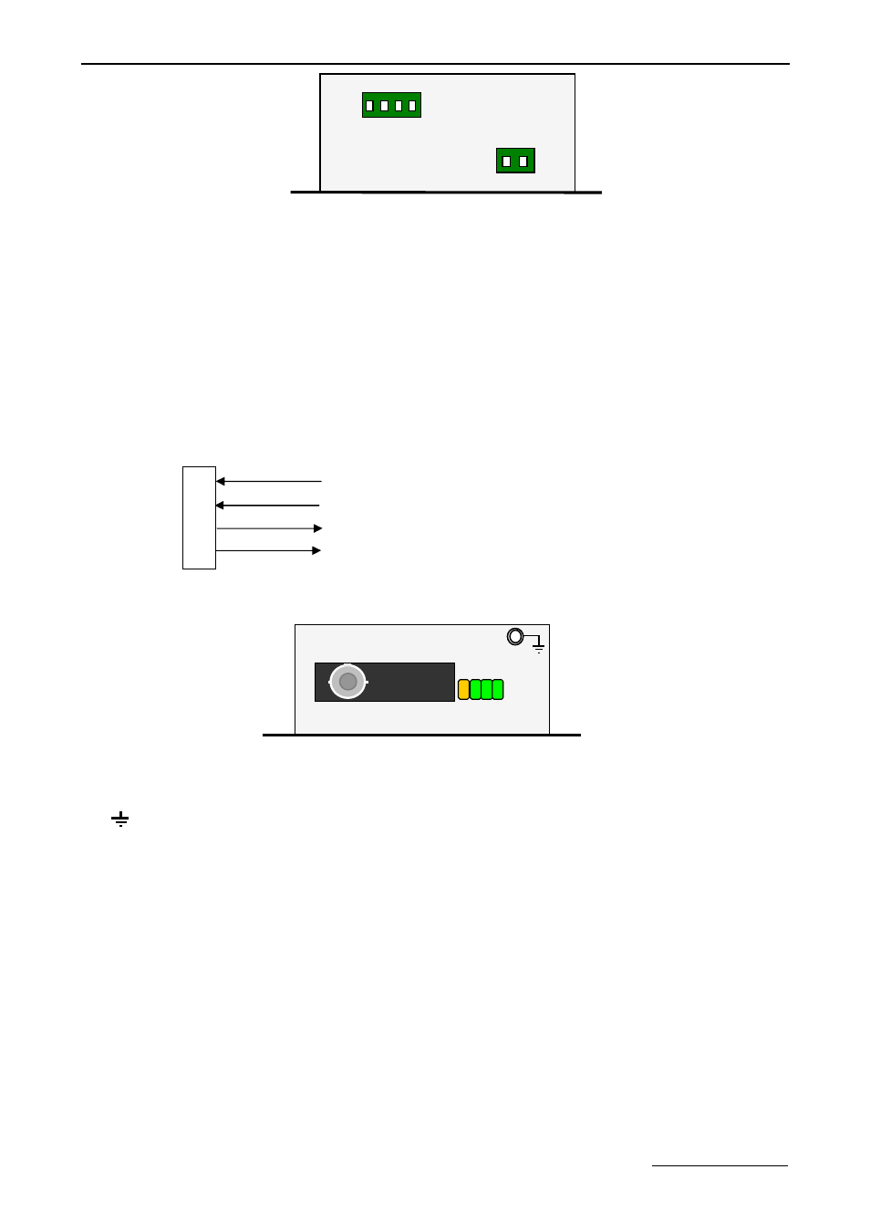
Receiver Left View
Connectors:
FIB: Fiber Optic.
: Ground Pin.
LEDs Definition:
FIB: Fiber Link. Off if link continuity is good.
On if no link continuity.
DATA1: Opposite Contact Closure. On if the contact node is closed.
DATA2: Positive Contact Closure. On if the contact node is closed.
1
2
3
4
FIB
F
IB
N
A
D
A
T
A
1
D
A
T
A
2
C1 C2
1 2 3 4
12~24V
+
-