Receiver enclosure – KBC Networks Compact Transceiver User Manual
Page 17
Compact Transceiver User Manual
Manual-Fx_MSeries-Rev1008.pdf Page 13 of 30
Copyright © KBC Networks Ltd.
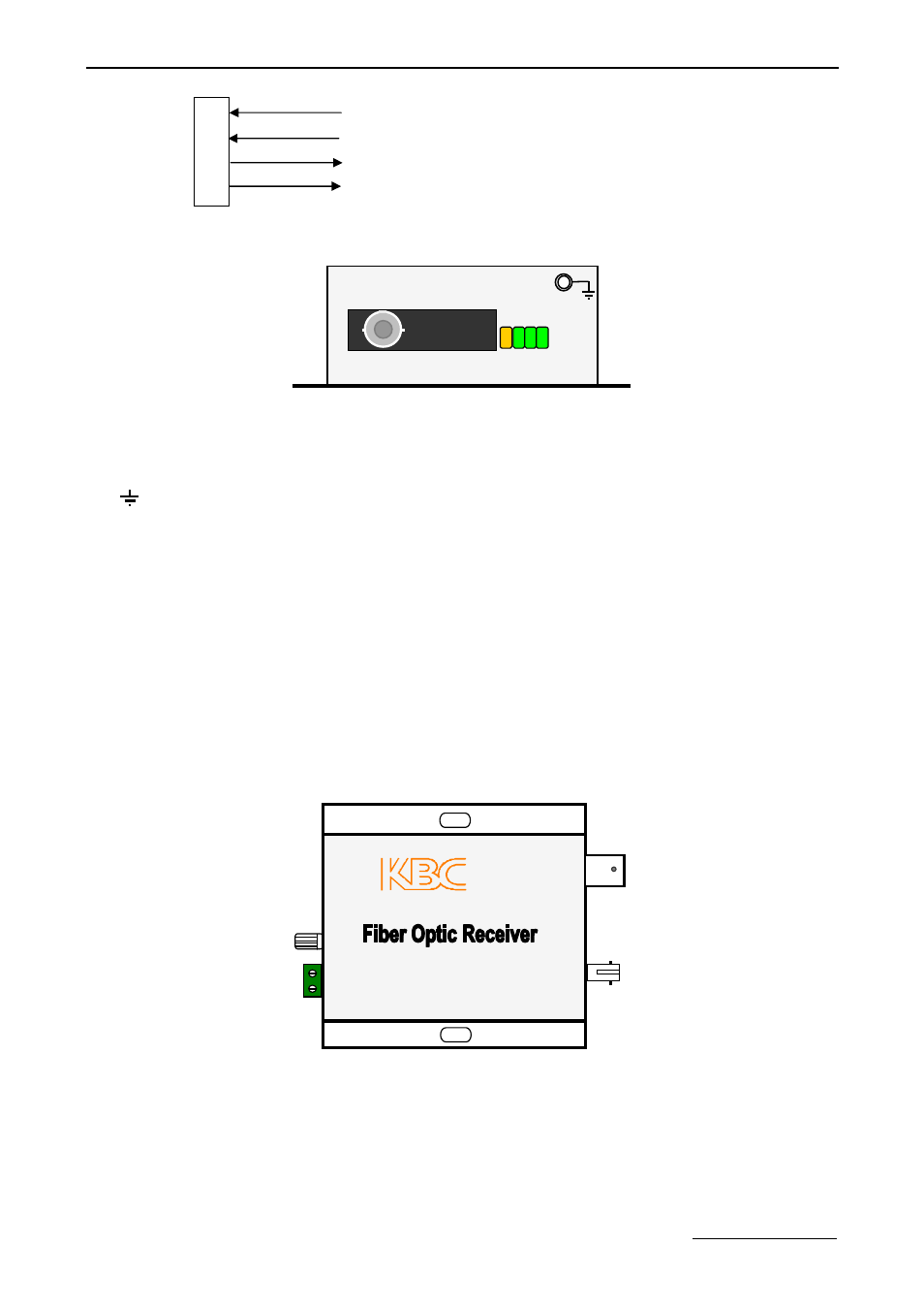
Terminal pins assignment as below:
Contact closure input
“A”
Contact closure input
“B”
Contact closure output
“A”
Contact closure output
“B”
12~24V: Power Supply refers to section 5. Power Input Specifications.
Transmitter Left View
Connectors:
FIB:
Fiber Optic.
: Ground Pin.
LEDs Definition:
FIB: Fiber Link. Off if link continuity is good.
On if no link continuity.
DATA1: Positive Contact Closure. On if the contact node is closed.
DATA2: Opposite Contact Closure. On if the contact node is closed.
4. Receiver Enclosure
4.1 Video Receiver
4.1.1 8 Bit Video Receiver
Receiver Top View
1
2
3
4
FIB
F
IB
N
A
D
A
T
A
1
D
A
T
A
2
- FTL1-S1A-B-MSE (10 pages)
- MCG1-S2-BS (8 pages)
- ThruLink SP (2 pages)
- VPS Solar Power Kits (12 pages)
- MiniLink (15 pages)
- MeshII (2 pages)
- Mesh2HT (59 pages)
- WES (19 pages)
- WES (18 pages)
- WES2HT 17dBi Point-to-Point Client / Host 5GHz (2 pages)
- WES2HT 2/5dBi Point-to-Multipoint Host with PoE (2 pages)
- WES2HT 9dBi Multipoint Host (2 pages)
- WESII 9dBi to 9dBi Kit (5 pages)
- WESIIKT V221 17dBi to 17dBi Kit (4 pages)
- H.264 Encoder (2 pages)
- H.264 Encoder (49 pages)
- MPEG-4 Decoder (2 pages)
- MPEG-4 Encoder (2 pages)
- MPEG4 Decoder (29 pages)
- MPEG4 Encoder (33 pages)
- WES2HT (142 pages)
- ESML3-FL2-D4 (18 pages)
- ESML6-FL2 (64 pages)
- ESUL6-FL2 (20 pages)
- ESML6-P3 (17 pages)
- ESML6-P3 (49 pages)
- ESML6-P3 (51 pages)
- WESII (141 pages)
- ESUG4P-PG2 (15 pages)
- ESUG8P (14 pages)
- ESUL4-FL1 (17 pages)
- ESUL5 (15 pages)
- ESML8P-PC2 (110 pages)
- ESUL8 (14 pages)
- ESUL5P (14 pages)
- EE2CL (19 pages)
- ESUL8P-PC2 (15 pages)
- EE1CL (17 pages)
- EE1R3 (12 pages)
- FCHA1-M1T-R-WSB (13 pages)
- FDVA2-S2T-R-WSC (11 pages)
- FDVA4-DB1-S1T-R-WSC (14 pages)
- 3U Chassis Transceiver (40 pages)
- FDVA4-S1T-R-WSC (11 pages)