KBC Networks WES User Manual
Page 7
Wireless Ethernet PtP & MP System Operations Manual
WIRELESS ETHERNET SYSTEM DETAILS (CONTINUED)
OMNI-DIRECTIONAL WEM (WAPOM / WSUOM)
A. SIDE VIEW
1. Antenna Dome Cover
2. Channel Selector
(Underneath plastic cap)
Factory set to channel 0
unless otherwise noted
3. LAN Port
4. Mounting Holes
Rear view is identical to the directional WEM
The WAPOM and WSUOM are not weatherproof when mounted outdoors without an
additional SWE-O (or other NEMA rated enclosure) housing. See SWE-O mounting
instructions for proper installation of the WAPOM/WSUOM in the outdoor housing.
POWER INJECTION MODULE (PIM)
Note: The Power Injector Modules are not weatherproof units and must be protected from moisture.
PIM DESCRIPTION
A. FRONT VIEW
PoE NOTIFICATION
The WEMs are mid-span compliant and must be powered using the supplied
power injection module. If an 802.3af compliant PoE switch is used, connect to
a non-PoE port of the switch only.
4
Wireless Ethernet PtP & MP System Operations Manual
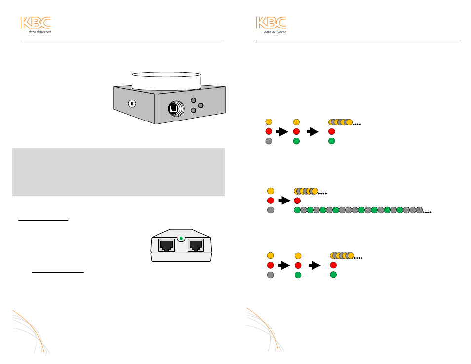
WES LED PATTERNS
For all units, the red power LED will either be active to show that it is powered up or off
to indicate no power. The link LED (Link Activity), or the amber LED, will flash rapidly
when there is activity across the wireless connection. The green LED, or Signal Level,
will illuminate upon connection. There are a few different regular Signal Level LED
responses determined by the type of product in use:
POINT TO POINT HOST LED ACTIVITY (WES-2500 & WES-2-4 Hosts)
If the green LED flashes at any rate it is indicating a less than max signal connection.
MULTIPOINT HOST LED ACTIVITY (WAP / WAPOM)
CLIENT LED ACTIVITY (All Clients from all part numbers excluding WAP/WAPOM)
The Client LED status will remain the same regardless of the type of host to which it
is connected. The Signal Level LED should remain solid to indicate a max signal
alignment. If the green LED flashes at any rate it is indicating a less than max signal
connection. A flashing green LED can be corrected by further alignment of the Client
to its Host.
5
1
3
1. DATA IN – Connect to Ethernet Device
2. POWER LED – Indicates power is on when lit
3. P+DATA OUT – Connect to the WEM
4. Power supply input (in rear of PIM)
2
3
4
1
Upon power
and cable
connection
Upon
connection to
Client
Upon
video
stream
LED activity if connected to 4 Clients
Upon power
and cable
connection
Upon connection to Client(s)
And video streaming or other
activity
Upon power
and cable
connection
Upon
connection
to Host
Upon
video
stream
FAQ: How can I tell the difference between an omni-directional and
directional WEM?
The difference in appearance between an omni-directional WEM (WAPOM and
WSUOM part numbers)and a standard directional WEM (WES-2500, WES-2-4, WAP,
WSU, WSUP) is the antenna dome cover. The omni antenna has a small dipole
under the dome cover and is about a 0.25 (7mm) inch taller than the directional
antenna dome cover.
1
2
3
4