DynaScan Outdoor 360 Degree LED Video Display DS1713 User Manual
Page 13
Copyright
©
2007-2013 DynaScan Technology Corp. 7
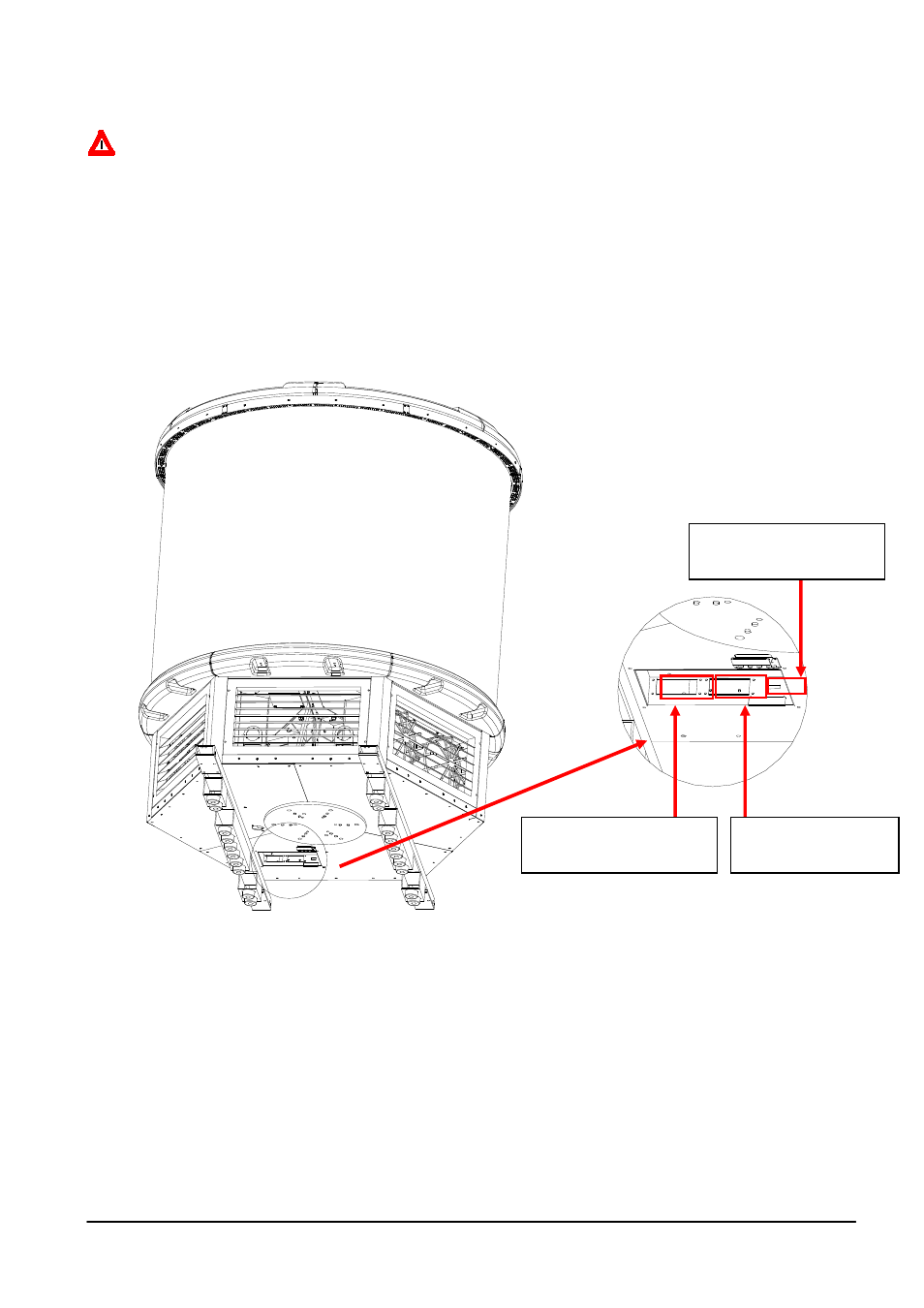
2.3 Connection diagram of the connectors on the
bottom of the base
CAUTION:
The power connectors must be connected to the correct connector as the
figure below or the display would be short-circuit.
From left to right:
Connector A is the cooling system connector.
Connector B is the system main power connector.
Connector C is the Giga Fiber Cable connector.
A. Cooling system
connector
B. System main
power connector
C. Giga Fiber Cable
connector