CRU DataPort 41 User Manual
Page 2
PMS 711
2 cyan
85 magenta
76 yellow
10.25.12
CRU Mark
1 Installation Steps
1.1 Frame Installation
a. Remove all hard drive sleds from the DataPort 41. Insert the DataPort 41 Key
into the slot on the front of each sled and push inwards. The sled will pop out
of its bay.
b. Slide the DataPort 41 frame into an open 5.25” bay in your computer system.
c. Use the provided mounting screws and a Phillips screwdriver to mount the
DataPort 41 frame into the computer chassis.
NOTE: The provided mounting screws are of a proprietary size. You
must use them in order to successfully mount the DataPort 41 frame into
the computer chassis.
d. Connect the SAS or SATA power and data connectors to the rear of the unit.
1.2 Hard Drive Installation
a. If you haven’t already done so, insert the DataPort 41 Key into the slot on the
front of the sled and push inwards. The sled will pop out of its bay.
b. Mount the hard drive to the sled using a Phillips screwdriver and the four
included hard drive mounting screws. Ensure that the drive’s data connector
is pointing through the hole in the rear of the sled.
c. Reinsert the sled into the open bay, and then push the sled handle down and
inwards so that it clicks into place.
d. You can optionally lock the sled into place. Insert the DataPort 41 Key into
the slot on the front of the sled. Without pushing inwards, rotate the key 90
degrees counterclockwise.
1.3 Operating Your DP41 Enclosure
a. a) Install the DataPort 41 frame into an open 5.25” bay in your computer
system. (See Section 1.1.)
b. Install your hard drives into the drive sleds. (See Section 1.2.)
c. Insert the sleds into the frame. As you do so, they will automatically power
on.
Your DataPort 41 enclosure is now ready to use! If the hard drives are already
formatted, they can be used right away. If the hard drive is brand new, or its
format is not compatible with your computer, the drive will need to be formatted
before being used. Note that formatting a drive will erase all data on the
drive, so be sure to back up your data before beginning this operation.
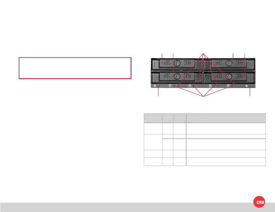
2 LED Behavior
Bay 1 Bay 2
Bay 4
Bay 3
HDD Bay #
Activity LED
HDD Bay #
Power LED
Fan LED
Unit Power
LED
LED Name
Color
State
Description
Fan
Red
Solid
Fan rotation is blocked, fan has failed, or no hard drives are
present inside the unit. If the fan has failed, please contact
Technical Support for a replacement fan.
HDD Bay #
Power*
Green
Solid
Hard drive has spun up and is receiving power.
Red
Solid
An error has been detected, which may be an incorrectly in-
stalled hard drive, a failed hard drive, or other issue. Please con-
tact Technical Support if you need help with troubleshooting.
HDD Bay #
Activity
Amber Blinking Hard drive data is being accessed.
Unit Power
Green
Solid
The DataPort 41 frame is receiving power through the computer
system’s motherboard.
*CRU allows OEMs and system integrators to customize the error condition using these LEDs for each drive. Please contact the OEM or
system integrator that you purchased this unit from for an explanation of the functionality of the error conditions.