CRU DE200 SCSI User Manual
Page 2
PMS 711
2 cyan
85 magenta
76 yellow
10.25.12
CRU Mark
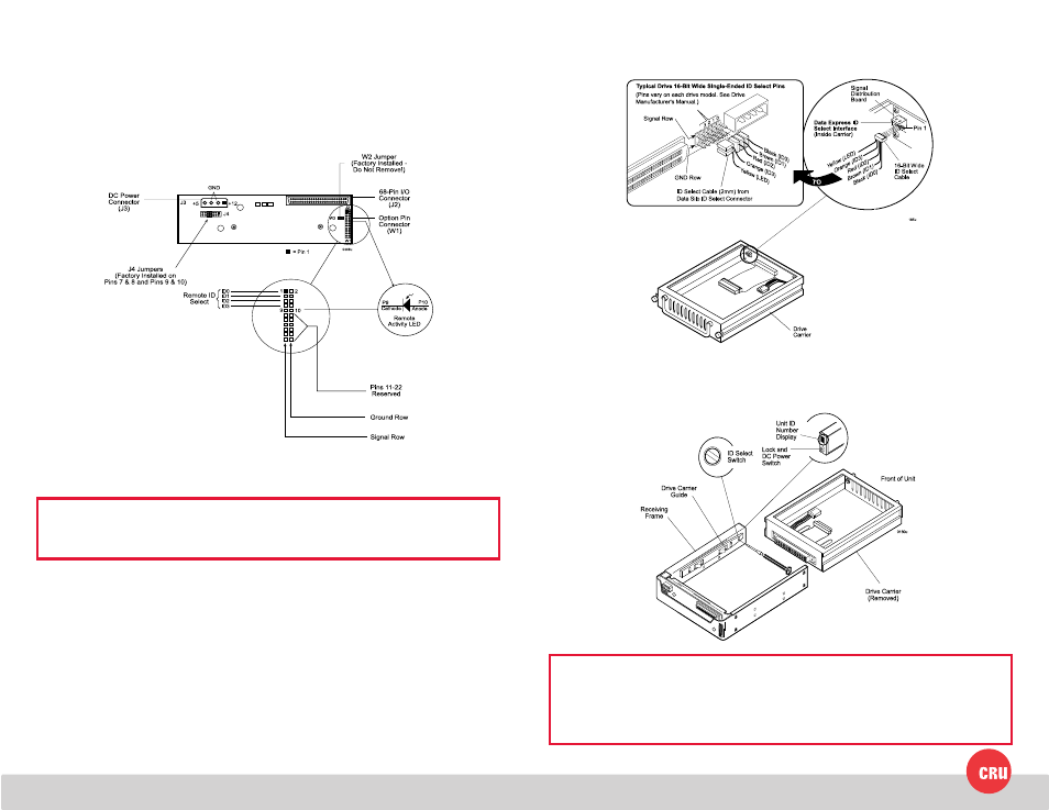
2 Receiving Frame Motherboard
Remote Unit ID Selection: Pins 1-8 are provided for remote unit ID selection for
the computer system or expansion chassis. Remote ID selection requires that the
unit ID switch located on the inside of the receiving frame be set to “0” (onboard ID
selection is set with a switch located on the inside of the receiving frame as shown
in Figure 10).
3 Typical SCSI ID Pin Connections
The figure below illustrates a typical SCSI ID select connection to a drive with 2mm
ID select pins. The wires on the wire harness connect to the positive pin (or signal
pins) on the disk drive. In some cases, the drive manufacturer will label the signal
pins as Pin 1, 3, 5, 7, (instead of 0, 1, 2, 3 as shown in Figure 3). Also, in some cases,
the even-numbered Pins 2, 4, and 6 are used for Ground.
Attach the ID select cable to the drive using the 2mm connectors. Align the “ID0”
pin with the black wire. Attach the 1.25mm connector on the other end of the
ID select cable to the 1.25mm connector (J3B) provided on the signal distribution
board, located inside the carrier. Refer to the manufacturer’s documentation to
disable termination on the drive.
4 Selecting the Unit ID Number
Use the alignment tool provided to select the ID number of the disk drive.
NOTE: The lock on the Data Express receiving frame functions as a lock and
a DC power switch for the carrier unit. The lock MUST be engaged (turned
counterclockwise) in order to supply power to the carrier and installed drive
unit.
NOTE: No onboard termination is provided on the DE200i-SWU2. External
termination must be provided.