CRU DE200 SCSI User Manual
Page 2
StorCase Technology, Inc.
D89-0000-0142
Rev. B00
Data Express DE200i-S
Data Express DE200i-S
D89-0000-0142
Rev. B00
StorCase Technology, Inc.
Unit
ID
Select
Switch
Location
Drive
Carrier
Guide
Receiving
Frame
Unit Select
Rotating
Switch
Drive
Carrier
(removed)
Unit
Number
Display
Lock
and DC
Power
Switch
Front of
Unit
0363
Typical
SCSI
ID
Select
Connections
(2mm
Drive
Pins)
Selecting the Unit ID Number: Use the alignment tool (provided) to select the ID number of the disk
drive.
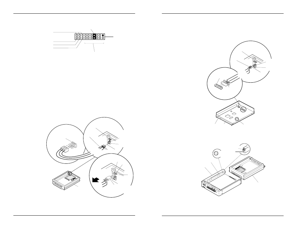
Typical 2mm Drive Pin Configuration
Figure below illustrates a typical SCSI ID select connection to a drive with 2mm ID select pins. Attach
the ID select cable to the drive using the 2mm connectors. Align the ID0 pin with the black wire. Attach
the 1.25mm connector on the other end of the ID select cable to the 1.25mm connector (J3B) provided
on the signal distribution board, located inside the carrier. In most cases, the drive manufacturer labels
the rows of SCSI ID select pins in their significant bit order (0, 1, 2, as shown in figure below). In other
cases, the manufacturer does not clearly label these pins in their significant bit order, but instead uses
pin numbers only. The wires on the wire harness connect to the positive pin (or sig-nal pins) on the disk
drive. In any case, either the odd numbered row of pins or the even numbered row of pins will be the
signal row. Refer to the device manufacturer's documentation for additional pin numbering and jum-
per option information.
0416
SCSI ID Select
Cable (from Data
Express Signal
Distribution Board)
1.25mm SCSI ID
Selection Connector J5
(located on disk drive
PCB)
SCSI I/O
Connector
Power
Connector
A0
A1
A2
SCSI ID Selection Pins
JP1 (located on disk
drive PCB)
When Using J5,
Remove All
Jumpers From JP1
R
e
s
e
r
v
e
d
G
n
d
Signal Distribution Board
ID
Select
Cable
Red (ID2)
Brown (ID1)
Black (ID0)
CARRIER BOARD
Inside Carrier
1.25mm Data
Express ID Select
Interface (J3B)
2mm Data Express
ID Select Interface
(J3A)
Typical
SCSI
ID
Select
Connections
(1.25mm
Drive
Pins)
Typical 1.25mm Drive Pin Configuration
Figure below illustrates a typical SCSI ID select connection to a drive with 1.25mm ID select pins. Connect
the 1.25mm ID select cable connector to the drive ID select pins. Attach each of the 2mm connectors on
the other end of the ID select cable to the 2mm connectors (J3A) provided on the signal distribution board,
located inside the carrier. Align the ID0 pin with the black wire of the cable. Refer to the device
manufacturer's documentation for additional pin numbering and jumper option information.
0426
Signal Distribution
Board
ID
Select
Cable
Red (ID2)
Brown (ID1)
Black (ID0)
DISK DRIVE
CARRIER
BOARD
1.25mm Data
Express ID Select
Interface (J3B)
2mm Data Express
ID Select Interface
(J3A)
To Drive ID
Select Pins
To ID
0
To ID
1
To ID
2
3-PIN WIRE WRAP
CONNECTOR (Provided). Use
in place of ID select cable
if there is not enough space.
Connects to J3.
Pin 1
J3
J6
(Reserved)
Carrier
Typical 2mm Drive ID Select Pins
(Pins vary on each drive model. See
Drive Manufacturer's Information.)
Receiving
Frame
Connector
(J4)
Pin
Configuration
0427
Receiving Frame
Mother Board
Connector J4
Installed
at Factory
Reserved
19
20
1
13
2
14
From System ID0
From System ID1
From System ID2
Ground
NOTE:
The lock on the Data Express receiving frame functions as a lock and a DC power switch for
the carrier unit. The lock MUST be engaged (turned counterclockwise) in order to supply power
to the carrier and installed drive unit.