Rtx220 qr - manual – CRU DX115 SAS/SATA 6G User Manual
Page 2
RTX220 QR - Manual
b. Insert the included Data Express Key into the keylock and turning it 90 degrees clockwise to
secure the carrier to the frame.
c. Press and hold the Power Button to power the unit on until the Drive Ready LED begins to
flash and the hard drive inside begins to spin up.
When any hard drive is first used with the DataPort 25 Secure it will show up as a blank,
unallocated drive and you’ll need to format the drive inside the enclosure before you can use it.
Note that formatting a drive will erase all data on the drive, so be sure to back up your
data before beginning this operation.
1.4 Safe Carrier Removal
a. Turn off the computer or properly dismount the drive from the system. Disconnecting the unit
without first unmounting the volume can result in data loss.
Mac Systems
Unmount the volume before powering down the unit by dragging the
volume’s icon to the trash bin, or by selecting the volume then pressing
Command-E.
Windows Systems
Unmount the DX115 before powering it down by left-clicking the green arrow icon on the task
bar (in Windows XP) or the USB plug icon with the green checkmark on the Desktop task bar
(Windows Vista, 7, 8), and then selecting the proper device from the menu that pops up. You
may have to click on the “Show Hidden Icons” arrow on the task bar to find the correct icon.
Windows will indicate when it is safe to disconnect the DataPort 25.
b. Use the DataPort Key to turn the keylock 90 degrees counter-clockwise to unlock and power
off the unit.
c. Push the eject button below the keylock once to release the button, and again to eject the
carrier.
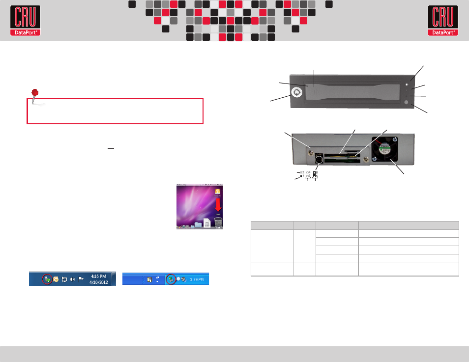
2 Identifying the Parts of Your DX115 6G
3 Other Configuration Options
3.1 LED Activity
*Some SATA PC systems/host controllers provide support for the Drive Activity LED feature (refer to the SATA PC
system/host controller manufacturer’s documentation for further information). The Drive Activity LED can be enabled
via host connection (cable not included) to Pin 1 located on Receiving Frame Motherboard (Figure 2). Refer to the SATA PC
system/host controller manufacturer’s documentation for further information.
3.2 Fan Error LED Disable Switch
This switch (see Figure 1) allows the user to disable the Fan Error LED (insert a paper clip or similar
object to activate switch). CRU-DataPort recommends replacing a faulty fan immediately. Contact
Technical Support to obtain a new fan.
NOTE: If the drive is already installed in the receiving frame before a system
power up, you do not have to press and hold the switch to power on the drive.
Figure 2 - DX115 Receiving Frame Rear Panel
Click-connect plate
GND
Host Activity
LED Pin
Reserved
Pins
HDD LED
Activity Disable
Cooling
Fan
SAS/SATA
Connector
Power Connector
Carrier Handle
Key Lock
Power Switch
Drive Ready/Error
LED
Drive Activity LED
Fan Error LED
Disable Switch
Push Here to Eject Carrier
Figure 1: Front Bezel
LED Name
Color
State
Description
Drive Ready/Error
Blue/Red Flashing Blue
Drive is inserted and powering up.
Solid Blue
Drive is powered on and ready for access.
Flashing Red and Blue Fan failure. Please contact Technical Support.
Solid Red
DC power failure. Please contact Technical Support.
Drive Activity
Amber
Flashing
Indicates when the host computer is accessing data on
the drive.*