Rugged, reliable, mobile, secure – CRU DE110 SATA 3G User Manual
Page 2
Rugged, Reliable, Mobile, Secure
TM
1-800-260-9800
www.CRU-DataPort.com
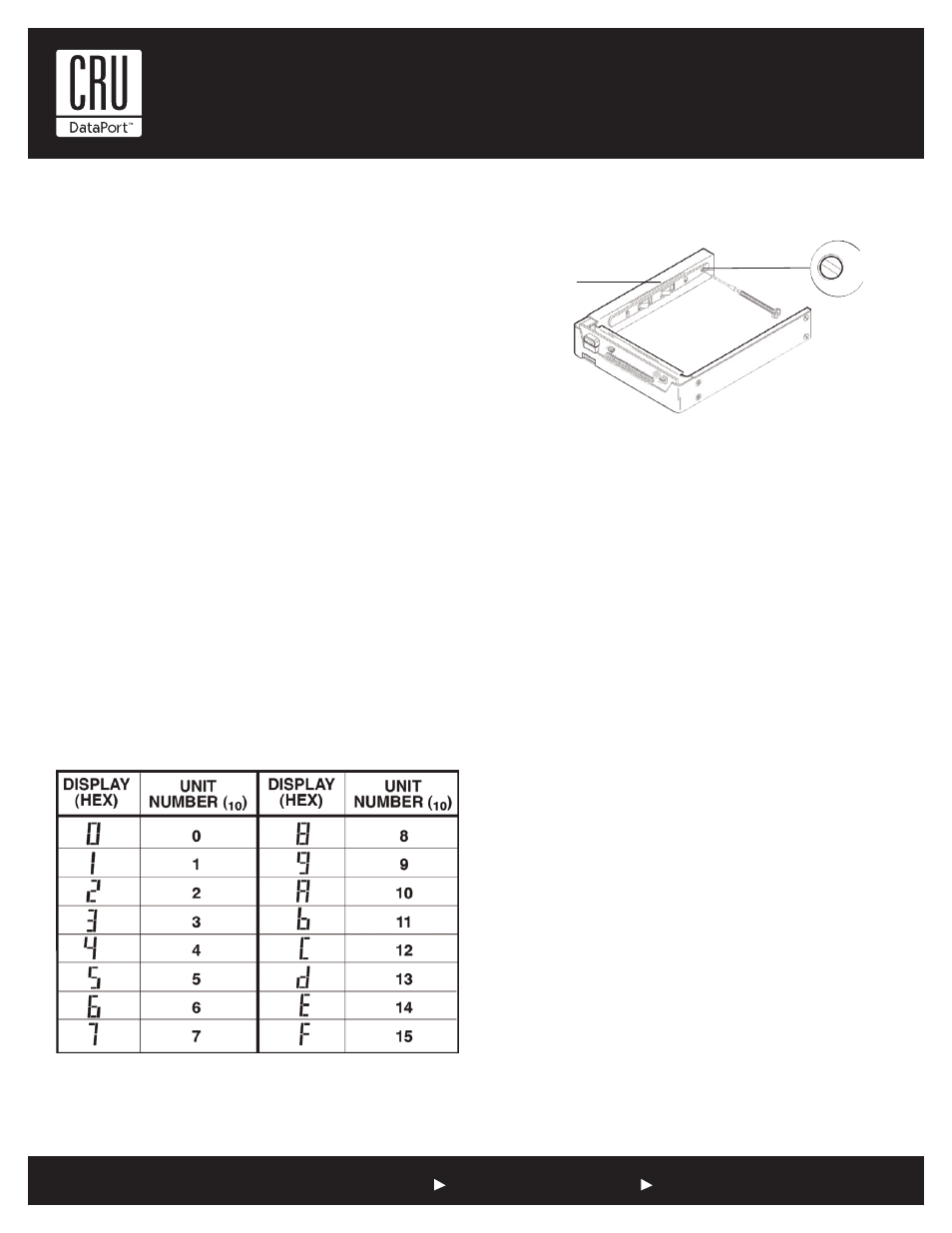
Selecting the Unit ID Number
Use the alignment tool (provided) to select the ID number of the
disk drive.
NOTE: The lock on the Data Express serves as a power
switch. It must be engaged (turned counterclockwise) for the
Data Express to power up and function properly.
Limited Product Warranty
CRU-DataPort (CRU) warrants the Data Express DE110 to be free of significant
defects in material and workmanship for a period of five years from the original
date of purchase. CRU’s warranty is nontransferable and is limited to the
original purchaser.
Limitation of Liability
The warranties set forth in this agreement replace all other warranties. CRU expressly
disclaims all other warranties, including but not limited to, the implied warranties of
merchantability and fitness for a particular purpose and non-infringement of third-party
rights with respect to the documentation and hardware. No CRU dealer, agent or em-
ployee is authorized to make any modification, extension, or addition to this warranty.
In no event will CRU or its suppliers be liable for any costs of procurement of substitute
products or services, lost profits, loss of information or data, computer malfunction, or
any other special, indirect, consequential, or incidental damages arising in any way out
of the sale of, use of, or inability to use any CRU product or service, even if CRU has
been advised of the possibility of such damages. In no case shall CRU’s liability exceed
the actual money paid for the products at issue. CRU reserves the right to make modi-
fications and additions to this product without notice or taking on additional liability.
Certification
EMI Standard:
FCC Part 15 Class B, CE
EMC Standard:
EN55022, EN55024
FCC Certification
This device has been tested and found to comply with the limits for a Class B
digital device, pursuant to Part 15 of the FCC rules. Operation is subject to the
following two conditions:
1. This device may not cause harmful interference.
2. This device must accept any interference received; including interference that
may cause undesired operation.
Register your product at www.CRU-DataPort.com
A7-110-0007 Rev. 1.1
Drive Activity LED
NOTE: Some SATA PC systems/host controllers provide
support for the Drive Activity LED feature (refer to the SATA
PC system/host controller manufacturer’s documentation for
further information).
The Drive Activity LED can be enabled via host connection (cable
not included) to Pin 1 located on the Receiving Frame Mother-
board (Figure 1).
Refer to the SATA PC system/host controller manufacturer’s
documentation for further information.
Spacer Plates (Optional)
The DE110 SATA 3Gb/s enclosure is designed to fit most comput-
er systems with standard 5.25” peripheral slots. The installation
of the spacer plates (provided) may or may not be necessary.
NOTE: Depending on the computer system, spacer plates
may be positioned on the receiving frame to utilize either
top or bottom row of side-mounting holes.
Unit ID Select Switch Settings
NOTE: The unit ID number display is for ID display pur-
poses only.
The following table lists the Unit ID Select Switch settings.
Figure 5: Unit ID Select
Switch Location
Figure 3: Unit ID Display Hex Reference
Drive Carrier
Guide
Typical Data Express
Receiving Frame
Unit ID Select
Rotating Switch