Rugged, reliable, mobile, secure – CRU DE75 68-pin U160 User Manual
Page 2
Rugged, Reliable, Mobile, Secure
TM
1-800-260-9800
www.CRU-DataPort.com
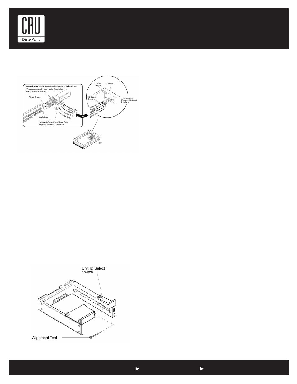
Figure 4: Unit ID Select Switch Location
NOTE: The lock on the Data Express serves as a power switch. It
must be engaged (turned counterclockwise) for the Data Express
to power up and function properly.
Limited Product Warranty
CRU-DataPort (CRU) warrants the Data Express DE75 to be free of sig-
nificant defects in material and workmanship for a period of five years
from the original date of purchase. CRU’s warranty is nontransferable
and is limited to the original purchaser.
Limitation of Liability
The warranties set forth in this agreement replace all other warranties. CRU
expressly disclaims all other warranties, including but not limited to, the
implied warranties of merchantability and fitness for a particular purpose
and non-infringement of third-party rights with respect to the documen-
tation and hardware. No CRU dealer, agent or employee is authorized to
make any modification, extension, or addition to this warranty. In no event
will CRU or its suppliers be liable for any costs of procurement of substi-
tute products or services, lost profits, loss of information or data, computer
malfunction, or any other special, indirect, consequential, or incidental
damages arising in any way out of the sale of, use of, or inability to use
any CRU product or service, even if CRU has been advised of the possibility
of such damages. In no case shall CRU’s liability exceed the actual money
paid for the products at issue. CRU reserves the right to make modifications
and additions to this product without notice or taking on additional liability.
Certification
EMI Standard:
FCC Part 15 Class B, CE
EMC Standard:
EN55022, EN55024
FCC Certification
This device has been tested and found to comply with the limits
for a Class B digital device, pursuant to Part 15 of the FCC rules.
Operation is subject to the following two conditions:
1. This device may not cause harmful interference, and
2. This device must accept any interference received; including
interference that may cause undesired operation.
Register your product at www.CRU-DataPort.com
A7-075-0003 Rev. 1
Figure above illustrates a typical SCSI ID select connection to a drive with
2mm ID select pins. The wires on the wire harness connect to the positive
pin (or signal pins) on the disk drive. In some cases, the drive manufac-
turer will label the signal pins as Pin 1, 3, 5, 7, (instead of 0, 1, 2, 3 as
shown in figure below). Also, in some cases, the even numbered Pins 2, 4,
6 are used for Ground.
Attach the ID select cable to the drive using the 2mm connectors. Align
the “ID0” pin with the black wire. Attach the 1.25mm connector on the
other end of the ID select cable to the 1.25mm connector (J3B) provided
on the signal distribution board, located inside the carrier. Refer to the
manufacturer’s documentation to disable termination on the drive.
Figure 3: Typical ID Select Connections (2mm Drive Pins)
Typical 2mm Drive ID Pin Configuration
Note: Applies to the DE75i-SW160 only.
Selecting the Unit ID Number
Use the alignment tool (provided) to select the ID number of the disk drive.