Conta-electronics – CONTA-CLIP CMS-UI-R User Manual
Page 2
CONTA-ELECTRONICS
=====
=
=
=
=
=
=
=
=
=
CMS
CMS
CMS
CMS----UI
UI
UI
UI----R
R
R
R
=
=====
=====
=====
=====IIIIsolated
solated
solated
solated S
S
S
Signal
ignal
ignal
ignal converter
converter
converter
converter
Further information:
www.conta-clip.com
Cat. No.: 95120.8
Further information:
www.conta-clip.com
Configuration
Configuration
Configuration
Configuration
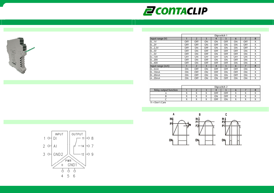
Dipswitch settings
Dipswitch settings
Dipswitch settings
Dipswitch settings
=
To open the module press the locking levers under the
terminals with a screwdriver.
The module is configured by setting the dip-switches according
to this manual and the table on the side of the module.
=
=
=
=
=
=
Connecting the module
Connecting the module
Connecting the module
Connecting the module
=
=
Re
Re
Re
Relay switching diagram
lay switching diagram
lay switching diagram
lay switching diagram
=
The pin configuration for I/O and power connection is shown on the top of the module.
DI input is not used.
Co
Co
Co
Connection diagram
nnection diagram
nnection diagram
nnection diagram
=
=
=
=
=
Set the threshold value of potentiometer P1 and P2 by using a screwdriver.
Both potentiometers represent a percentage from the selected input value.
Full left turn is 0% and full right turn is 100% of the selected input value.
A:
A:
A:
A: The relay switches on when value P1 is reached. The relays switches off when
value P1 - P2 is reached.
B:
B:
B:
B: The relay switches on when value P1 is reached. The relays switches off when
value P2 is reached.
C:
C:
C:
C: The relay switches on between P1 and P2.
=====