CIRCUTOR OPTIM-FR Series User Manual
Page 8
Instruction Manual
6
4.6
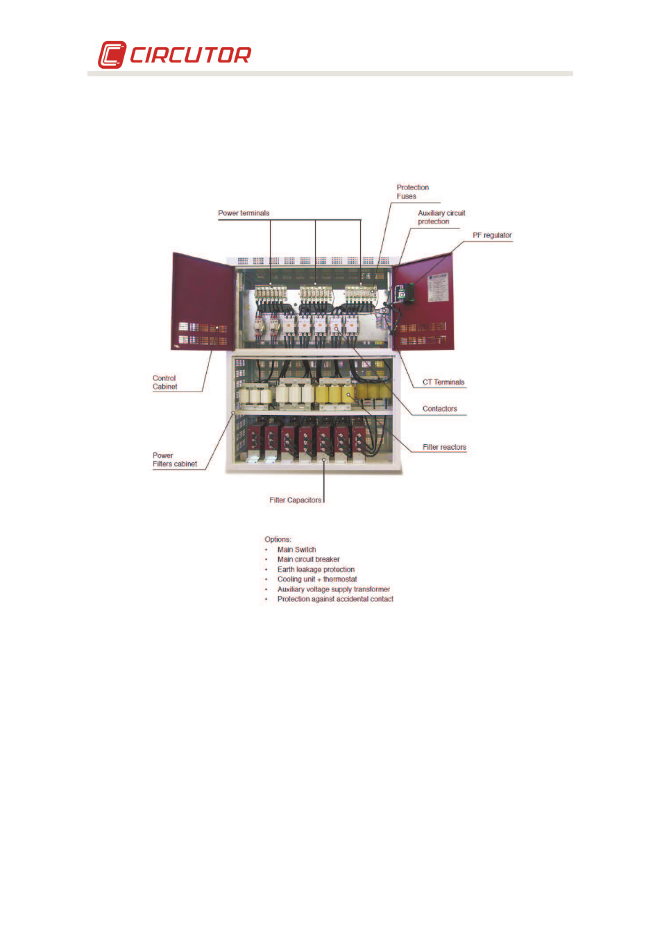
Filter bank components
Fig. 4-3 shows the different models of filter banks and their essential components. Some
protection elements are optional.
Fig. 4-3 .- FR Filter bank components
5
INSTALLATION
5.1
Preparation
CIRCUTOR's FR filter banks are prepared for an easy installation and start-up.
Remove the equipment's packaging and verify that the unit's electrical characteristics are
suitable for connection to the available grid. For this, check the characteristics at the label
located inside the cabinet, next to the regulator, refer to Fig. 4-1 as an example.
Key data to be checked:
-
Grid voltage and frequency, U
N
/ f.
-
Nominal power of the filter bank, Q
N
(kvar) and composition
-
Type of filter, identified by the p% factor (7%, 14%, ..., etc.)
-
Current consumption, I
max
(See label) . This current must be considered to select the
proper size of the supply cable circuit breakers and other protection devices to be
connected upstream the supply terminals.
-
Auxiliary control voltage, U
aux
(See section 4.2)
-
Environmental conditions. (See section 4.3)