CIRCUTOR OPTIM-FR Series User Manual
Page 11
Instruction Manual
9
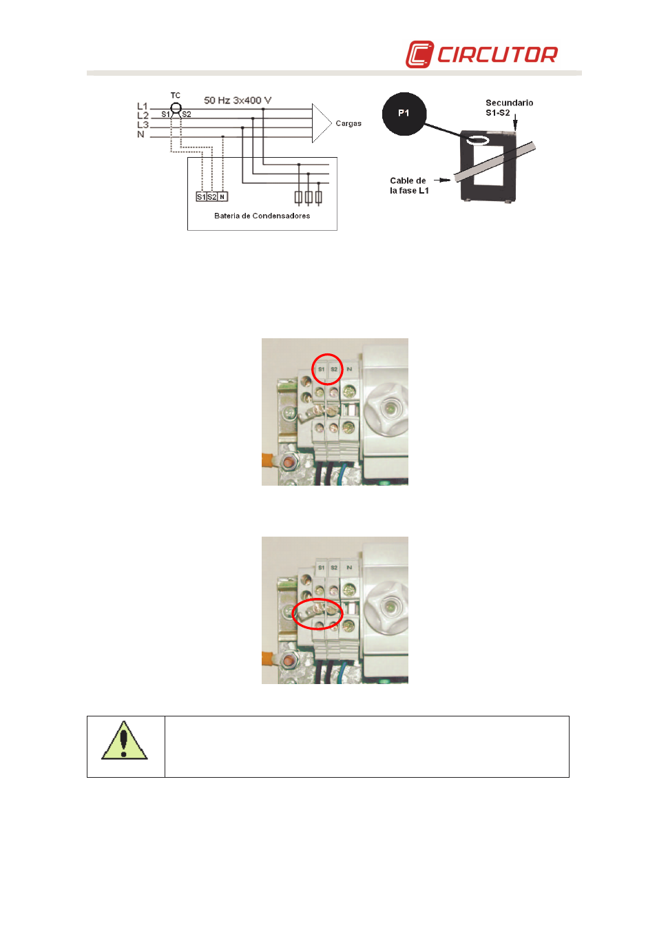
Fig. 5-3 .- Installation of the current transformer (TC) (external)
•
The connection point of the TC for a filter bank that compensates an entire installation is after
the installation's mains switch.
•
To prevent excessive attenuation of the signal, the minimum secondary cable section
(terminals S1, S2) should be at least 2.5 mm2.
Fig. 5-4 .- TC and neutral connection terminals if required
•
Once the cables are installed, disconnect the jumper connecting terminals S1 and S2 on the
filter bank (see Fig. 5-5)
Fig. 5-5 .- Jumper for short-circuiting the secondary winding of the current transformer (TC).
Any time you wish to change or disconnect a current transformer that is already
installed, it is important to install the jumper connecting S1 and S2.