CIRCUTOR T3V Series User Manual
Page 7
--------- EARTH RESISTANCE TESTER
T-3V
------- Page No. 6
-
3.2.- Use
Before starting measurements, carefully read the Safety Advice section.
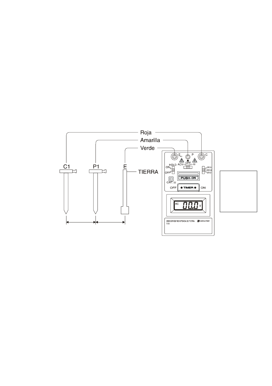
Connecting the test pins:
Connect the green, yellow and red test pins to the terminals E, P and C with the
earth rods P1, C1 placed in the ground "in a straight line" (see figure).
Place the function switch [7] onto the ACV position and ensure that the voltage
reading is less than 10 V AC. If not the accuracy of the earth resistance
measurement cannot be guaranteed.
If the PUSH-ON [9] button is pressed and the operating indicator [2] does not
come on, thisl means that there is an open circuit between the test pins.
200V
~
5 10m
~
5 10m
~
Place the range switch [8] on the appropriate scale and the function switch [7]
on position "
Ω". Then press PUSH-ON [9] and TIMER ON10] at the same time
and read the value on the indicator.
NOTE: When none of the E, P and C terminals is connected to the test pins, a
reading between 300 and 600 is normal (in function
Ω, range 2 kΩ).
Red
Yellow
Green
EARTH