Assembling the microtherm, 1 assembly, 2 sensors – Casella CEL Indoor air quality monitor User Manual
Page 6: Assembly
2.
ASSEMBLING THE MICROTHERM
The MICROTHERM control unit is supplied in a hard wearing carry case with
sufficient room to house the basic complement of sensors. Prior to use the
MICROTHERM must be assembled and programmed.
2.1
Assembly
To assemble the MICROTHERM prior to use, remove the control unit from the
carrying case and place on a secure level surface.
If fitted, remove the blanking plug from the hub mounting hole located on the
top cover of the control unit.
Locate the small hub over the mounting hole and secure using the hub retaining
screw.
Screw a sensor retaining arm into each of the four holes located in the small hub
making sure the sensor clip on each arm ends up in a vertical position. Lock
each arm in position using the ‘locking collar’ at the base of each arm.
2.2
Sensors
Arrange the required sensors using the available “sensor clips” and insert the
connector in the associated socket located on the back panel. Note that not all
the sensors can be mounted using the “sensor clips” and that some
combinations of sensors are not permissible as they use the same sockets.
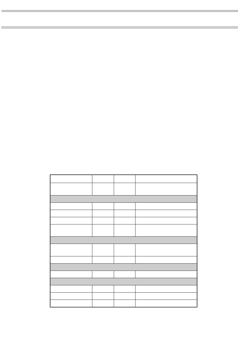
The following table outlines possible sensor allocations.
Sensor
Channel
Mount
Combination
Air Temperature
Relative Humidity
1
Clip
Combined sensor uses single
channel and clip
Natural Wet
2
Clip
Particulate
2
Tripod
Light Intensity
2
Clip
Particulate
Light Intensity
2
2
Tripod
Clip
Adapter allows both sensors to
share single channel connector.
Black Globe 40 mm
3
Clip
Use either the 40 mm or the
150 mm globe but not both.
Black Globe 150 mm 3
Clip
Air Velocity
4
Clip
Carbon Dioxide
5
Desk
Ozone
6
Desk
Carbon Monoxide
6
Desk
Assembly
Page 6 of 42
MICROTHERM indoor air quality &
WinIaq Application Software - User Manual