Technical description, 1 factory calibration and adjustment, 2 definition of usable volume – BINDER FDL 115 User Manual
Page 65: 3 technical data fdl 115
FDL (E2.1) 02/2015
page 65/75
17. Technical description
17.1 Factory calibration and adjustment
This unit was calibrated and adjusted in the factory. Calibration and adjustment were performed using
standardized test instructions, according to the QM DIN EN ISO 9001 system applied by BINDER (certi-
fied since December 1996 by TÜV CERT). All test equipment used is subject to the administration of
measurement and test equipment that is also constituent part of the BINDER QM DIN EN ISO 9001 sys-
tems. They are controlled and calibrated to a DKD-Standard at regular intervals.
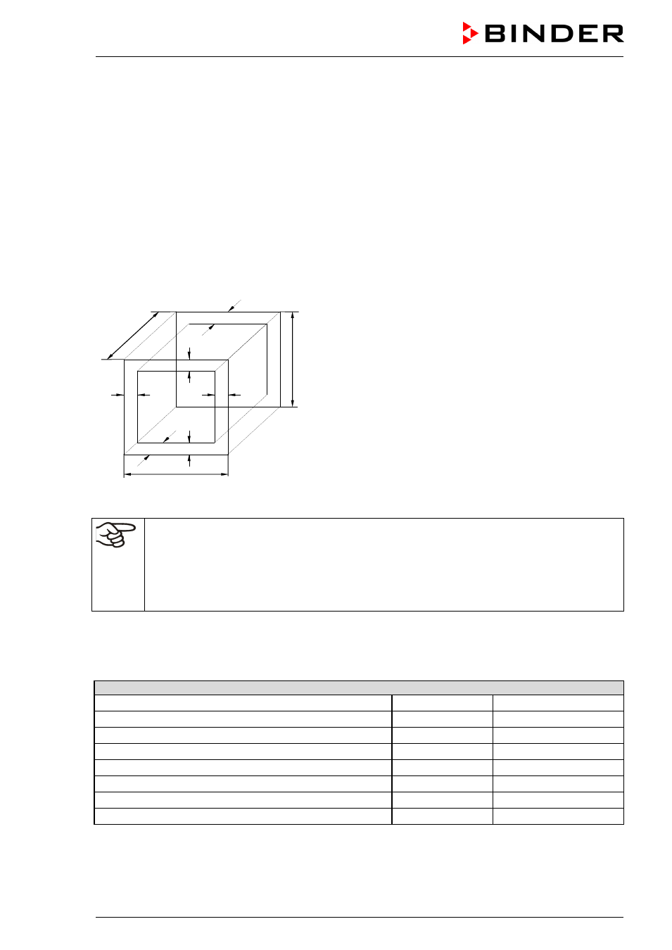
17.2 Definition of usable volume
The usable volume illustrated below is calculated as follows:
b
c
c
a
b
a
a
C
B
A
A, B, C = internal dimensions (W, H, D)
a, b, c = wall separation
a = 0.1*A
b = 0.1*B
c = 0.1*C
V
USE
= (A - 2 * a) * (B - 2 * b) * (C - 2 * c)
Figure 15: Determination of the usable volume
The technical data refers to the so defined usable volume.
Do NOT place samples outside this usable volume.
Do NOT load this volume by more than half to enable sufficient airflow inside the chamber.
Do NOT divide the usable volume into separate parts with large area samples.
Do NOT place samples too close to each other in order to permit circulation between them
and thus obtain a homogenous distribution of temperature and humidity.
17.3 Technical data FDL 115
Exterior Dimensions
Width
mm / inch
835 / 32.87
Height (including feet)
mm / inch
800 / 31.50
Depth
mm / inch
685 / 26.97
Additional depth of door handle
mm / inch
50 / 1.97
Wall clearance rear
mm / inch
100 / 3.94
Wall clearance side
mm / inch
160 / 6.30
Exhaust duct, outer diameter
mm / inch
100 / 3.94
Total steam space volume 1)
l / cu.ft.
156 / 5.51