3 inputs and outputs, 1 connector pin diagram – Applied Motion TSM23P-2AG User Manual
Page 14
14
Rev. A
920-0083
TSM23P Hardware Manual
3.3 Inputs and Outputs
All drives include 4 digital inputs
• X1/STEP & X2/DIR are high-speed 5-24 volt logic digital inputs for commanding position.
Quadrature signals from encoders can also be used.
• X3/EN and X4/AR are 5-24 volt logic digital inputs. X3/EN is used for motor enable/disable.
X4/AR is used for alarm reset.
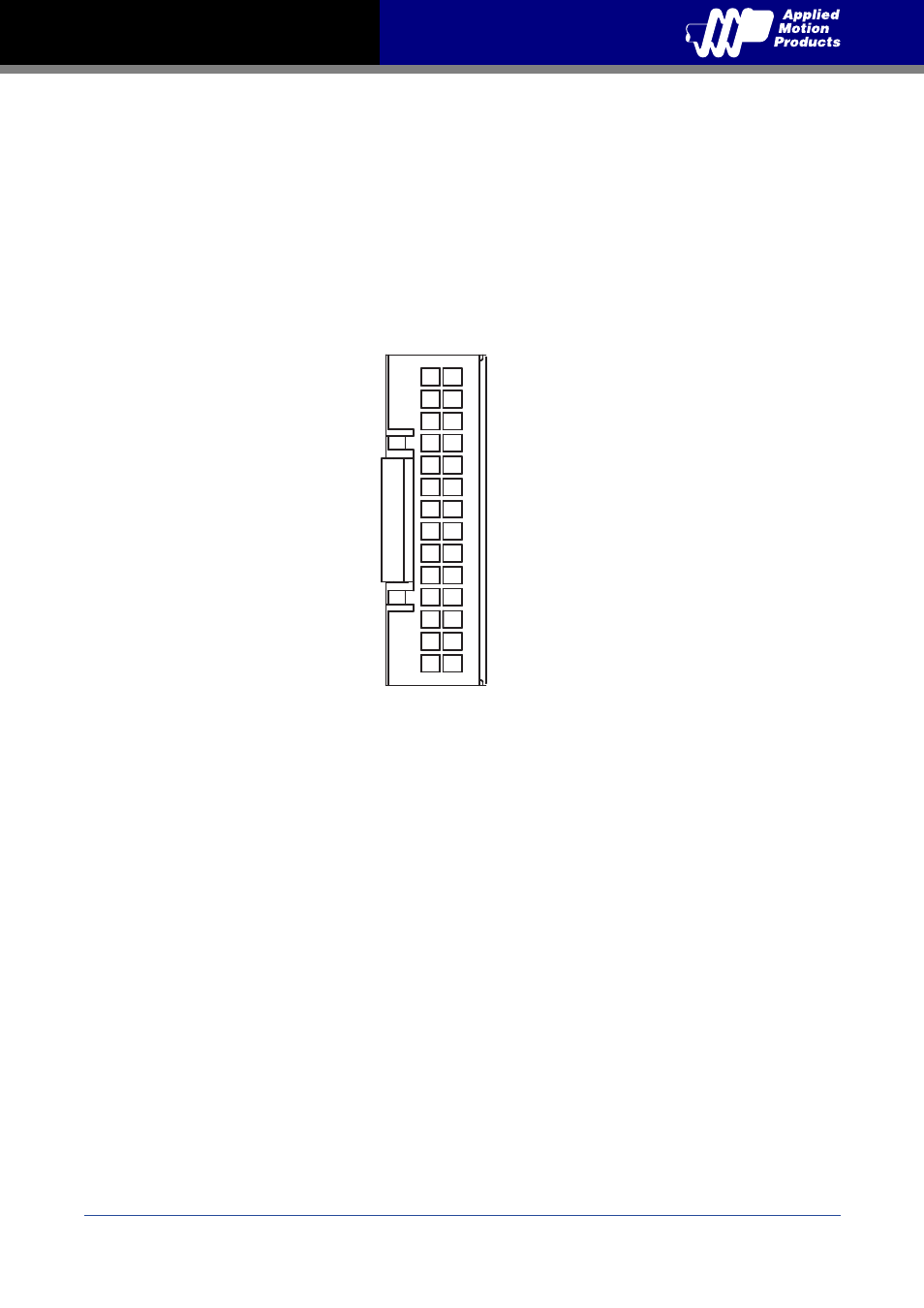
3.3.1 Connector Pin Diagram
ENC A-
ENC B-
ENC Z-
NC
YCOM
Y2/IN POSITION
NC
NC
NC
NC
NC
X4/ALARM RESET
X2/DIR-
X1/STEP-
ENC A+
ENC B+
ENC Z+
NC
Y3/BRAKE
Y1/ALARM
NC
NC
NC
XCOM
NC
X3/SERVO ON
X2/DIR+
X1/STEP+
27 28
1 2
This manual is related to the following products: