2 connecting the tsm17p communications, 1 connecting to the pc using rs-232, 3 inputs and outputs – Applied Motion TSM17P-1AG User Manual
Page 13: 1 connector pin diagram
13
Rev. A
920-0086
TSM17P Hardware Manual
3.2 Connecting the TSM17P Communications
The TSM17P comes with a cable that will provide the interface to an RS-232 port through a DB9
style connector.
3.2.1 Connecting to the PC using RS-232
Locate the TSM17P within 2.5 meters of the PC. Plug the DB9 connector of the communication
cable that came with the drive into the serial port of the PC. Plug the small end into the crimp style
connector on the TSM17P . Secure the cable to the PC with the screws on the DB9 connector.
Note: If the PC does not have an RS-232 serial port, a USB Serial Converter will be needed.
You can contact Applied Motion Products to buy a USB to RS-232 converter.
The RS-232 circuitry does not have any extra electrical “hardening” and care should be taken
when connecting to the RS-232 port as hot plugging could result in circuit failure.
3.3 Inputs and Outputs
TSM17P drives include 4 digital inputs
X1/STEP & X2/DIR are high-speed 5-24 volt logic digital inputs for commanding position.
Quadrature signals from encoders can also be used.
X3/EN and X4/AR are 5-24 volt logic digital inputs. X3/EN is used for motor enable/disable. X4/AR
is used for alarm reset.
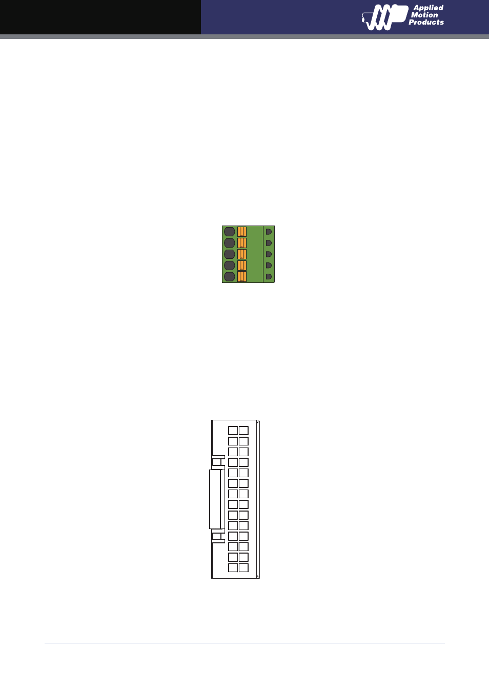
3.3.1 Connector Pin Diagram
RXD
+5V
TXD
GND
GND
ENC A-
ENC B-
ENC Z-
NC
YCOM
Y2/IN POSITION
NC
NC
NC
NC
NC
X4/ALARM RESET
X2/DIR-
X1/STEP-
ENC A+
ENC B+
ENC Z+
NC
Y3/BRAKE
Y1/ALARM
NC
NC
NC
XCOM
NC
X3/SERVO ON
X2/DIR+
X1/STEP+
27 28
1 2