3 inputs and outputs, 1 connector pin diagram, Ssm23q/ip hardware manual – Applied Motion SSM23IP-2EG User Manual
Page 22
22
Rev.A
920-0090
SSM23Q/IP Hardware Manual
3.3 Inputs and Outputs
The SSM23Q/IP has three types of inputs:
• High speed digital inputs for step & direction commands or encoder following, 5 to 24 volt logic
• Low speed digital input for other signals, 5 to 24 volt logic
• Analog input for analog speed and positioning modes
All drives include 3 digital inputs and 1 analog input
• STEP & DIR are high-speed digital inputs for commanding position. Quadrature signals from
encoders can also be used. When not being used for the Step & Direction function these
inputs can be used for CW & CCW Limit, CW & CCW Jogging and Run/Stop & Direction
Velocity modes.
• EN is a low speed software programmable input and can be used for Motor Enable and/or
Alarm Reset. This input can also be connected to a sensor, switch or other device for use with
Wait Input (WI), Seek Home (SH), Feed to Sensor (FS), On Input (OI) and other commands.
• AIN is an analog input for a velocity or position command signal. It can accept 0-5 volts and
has gain, filtering, offset and dead-band settings.
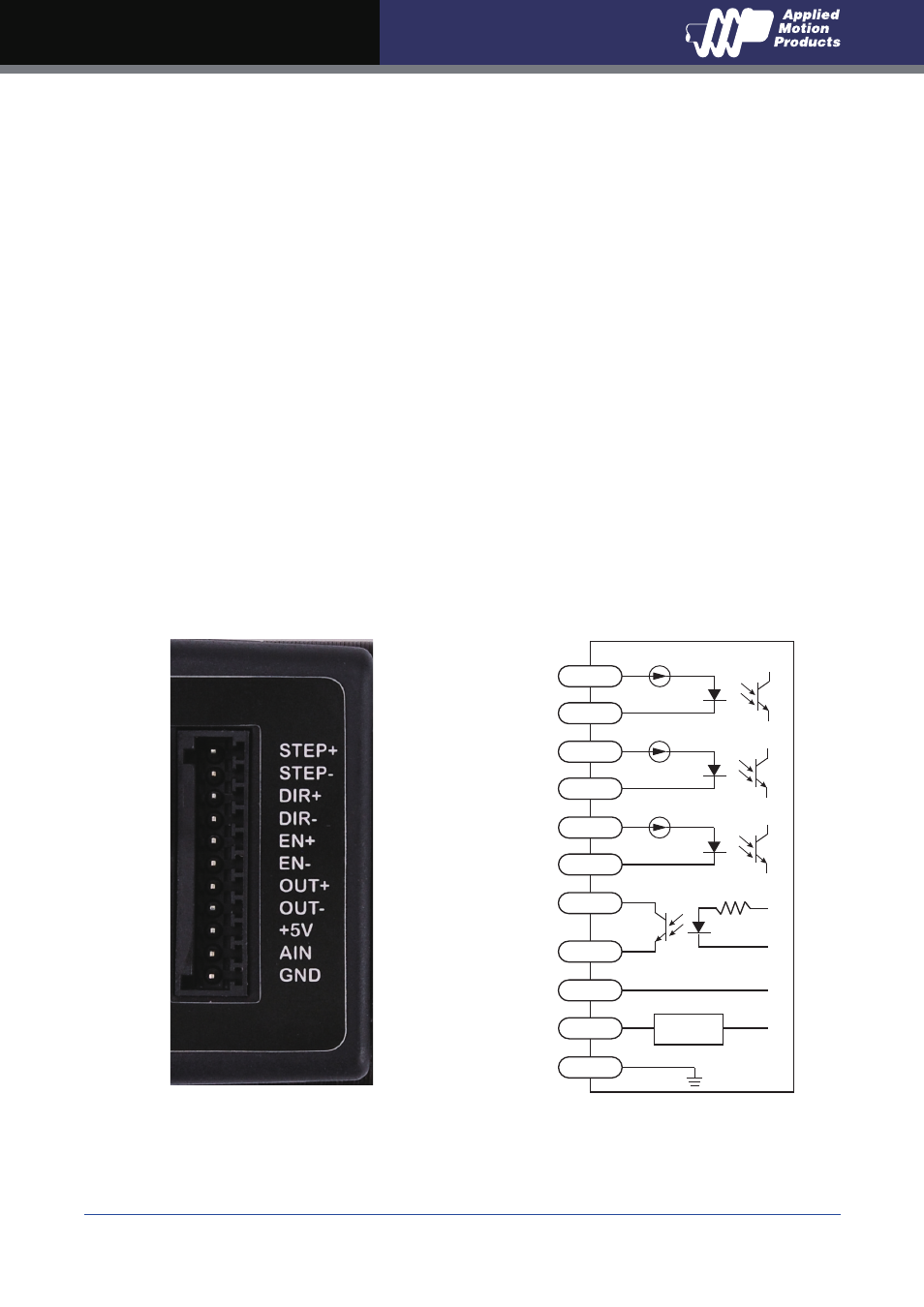
3.3.1 Connector Pin Diagram
IN/OUT Connector
inside drive
STEP+
STEP-
DIR+
DIR-
EN+
EN-
OUT+
OUT-
Res
+5V
100mA Limit
AIN
Signal
Conditioning
GND