Applied Motion ST10-C-CE User Manual
Page 27
27
ST5/10-Si,-Q,-C, IP Hardware manual
920-0004 Rev. F
6/10/14
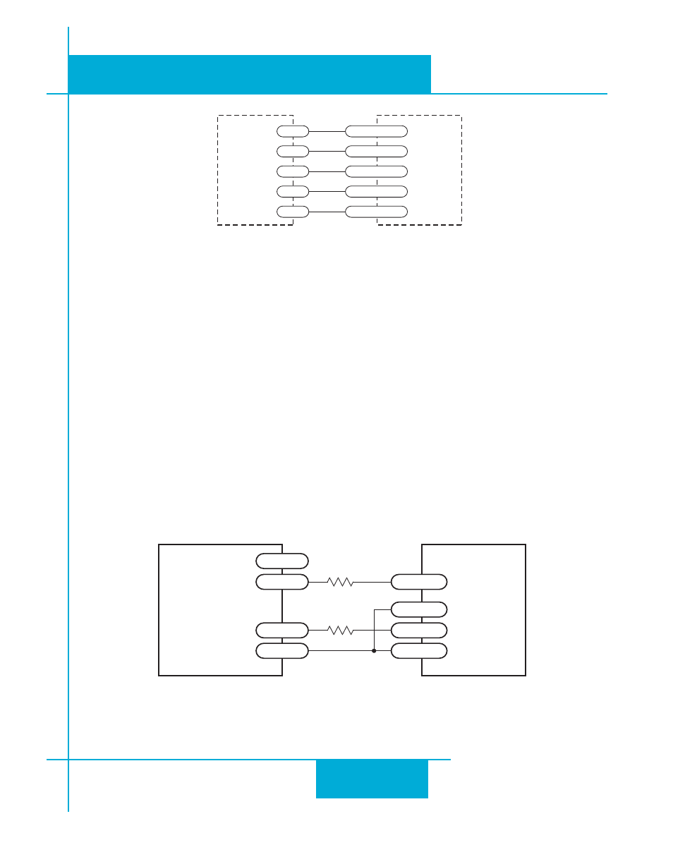
Connecting to PLC with Sourcing (PNP) Outputs
(Most PLC’s use 24 volt logic)
DRIVE
+12-24V
GND
X2/DIR-
OUT1
X2/DIR+
X1/STEP-
OUT2
X1/STEP+
PLC
with
Sourcing
Outputs
R
R
Wiring for Encoder Following
Using High Speed Inputs with 12-24 Volt Signals
Most PLCs don’t use 5 volt logic. You can connect signal levels as high as 24 volts to the STEP and DIR
inputs if you add external dropping resistors, as shown below.
• For 12 volt logic, add 820 ohm, 1/4 watt resistors
• For 24 volt logic, use 2200 ohm, 1/4 watt resistors
The maximum voltage that can be applied to an input terminal is 24 volts DC.
Never apply AC voltage to an input terminal.
-Si or -Q
drive
Master
Encoder
GND
X2/DIR-
X2/DIR+
X1/STEP-
X1/STEP+
GND
B-
B+
A-
A+