Electrical characteristics curves – Delta Electronics Series 240W User Manual
Page 6
DS_E48SB9R625_05222008
6
ELECTRICAL CHARACTERISTICS CURVES
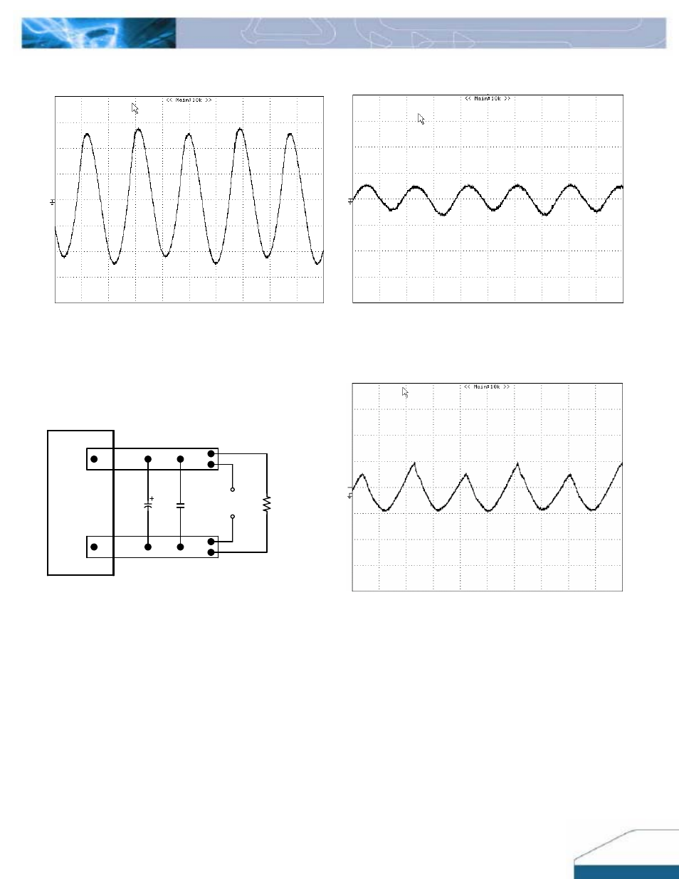
Figure 11:
Input Terminal Ripple Current, i
c
, at full rated output
current and nominal input voltage with 10µH source impedance
and 47µF electrolytic capacitor (200 mA/div, 2us/div).
Figure
12:
Input reflected ripple current, i
s
, through a 10µH
source inductor at nominal input voltage and rated load current
(20 mA/div, 2us/div).
Vo(-)
Vo(+)
10u
1u
Copper Strip
SCOPE
RESISTIVE
LOAD
Figure 13:
Output voltage noise and ripple measurement test
setup.
Figure 14:
Output voltage ripple at nominal input voltage and
rated load current (50 mV/div, 2us/div). Load capacitance: 1µF
ceramic capacitor and 10µF tantalum capacitor. Bandwidth: 20
MHz. Scope measurement should be made using a BNC cable
(length shorter than 20 inches). Position the load between 51
mm to 76 mm (2 inches to 3 inches) from the module.
0
0
0
- AC Motor Drive VFD-G (183 pages)
- SMT Power Inductor SIL104R (1 page)
- Q48SB (2 pages)
- Planar DC/DC Transformer ER/ER(Plate) 22 (1 page)
- SMT Power Inductor HCB1190B (1 page)
- Series E48SR (15 pages)
- E48SR12007 (15 pages)
- SMT Power Inductor SIWC1360 (1 page)
- PFC Chokes PFC2815V Series (1 page)
- SMT Power Inductor SIB86 (1 page)
- PMC-24V050W1AA (2 pages)
- SMT Power Inductor HCB1050 (1 page)
- SMT Power Inductor HAH1330 (1 page)
- PFC Chokes PFC4120V Series (1 page)
- PFC Choke PFC3520V Series (1 page)
- SMT Power Inductor HCB1047B (1 page)
- SMT Power Inductor HAH1365 (1 page)
- SMT Power Inductor HMS1355 (1 page)
- Series S48SA (13 pages)
- E48SC (2 pages)
- SMT Power Inductor SILM106 (1 page)
- Delphi Series L48DB (2 pages)
- S48SA (13 pages)
- E36SR (2 pages)
- 3KVA (31 pages)
- SMT Power Inductor HMU1056L (1 page)
- Through Hole Power Inductors THCBR1090 (1 page)
- SMT Power Inductor SIL625 (1 page)
- SMT Power Inductor 1378(S) (1 page)
- Through Hole Power Inductors 1411 (1 page)
- Current Sense Transformers TCE1310H (1 page)
- H48SR (13 pages)
- Series E48SH (15 pages)
- AC Motor Drive VFD-EL (209 pages)
- Through Hole Power Inductors THAH1095 (1 page)
- Suppression Inductors LFU09V (1 page)
- SMT Power Inductor HCB0740A (1 page)
- Power Output Module DVPPS01 (2 pages)
- SMT Power Inductor SIR74 (1 page)
- L36SA (2 pages)
- 4.5V~ 5.5V (3 pages)
- Delphi Series V48SB (2 pages)
- Series S48SP (14 pages)
- Delphi Series E24SR (15 pages)