Nexen FMCBE-875 801428 User Manual
Page 6
6
FORM NO. L-20150-V-1112
MOUNTING BETWEEN A GEAR REDUCER AND A
MOTOR
1. Insert the Key (Item 25) into the output shaft of the
FMCBE (See Figure 3).
2. Slide the FMCBE output shaft into the gear reducer
(See Figure 3).
3. Secure the FMCBE to the gear reducer, using customer
supplied socket head cap screws, lock washers, and
nuts (See Figure 3).
NOTE: Model 625 does not have a Female Pilot;
proceed with Step 5 for this model.
4. On Models 875, 1125, and 1375, first remove the
Socket Head Cap Screws (Item 27 on Models 875 and
1125 or Item 13 on Model 1375) and Female Pilot (Item
26); then, secure Female Pilot to the motor face using
Socket Head Cap Screws (Item 29) and Lock Washers
(Item 30) and tighten them to the recommended torque
(See Figure 1 and Table 1).
5. Insert the customer supplied key into the motor shaft
keyway (See Figure 3).
6. Slide the FMCBE 625 onto the motor shaft (See Figure
3).
7. On Model 625, secure the FMCBE to the motor using
Socket Head Cap Screws (Item 29) and Lock Washers
(Item 30) and tighten them to the recommended torque
(See Figure 2 and Table 1).
Apply a drop of Loctite
®
242 to the threads of the
Socket Head Cap Screws (Item 27 on Models 875
and 1125 or Item 13 on Model 1375).
On Models 875, 1125, and 1375, secure the FMCBE
Housing (Item 1) to the Female Pilot (Item 26) using
Socket Head Cap Screws (Item 27 on Models 875
and 1125 or Item 13 on Model 1375) and tighten them
to the recommended torque (See Figure 1 and Table
1).
8. Align the hole in the FMCBE Housing (Item 1) with the
tapped hole in the Drive Disc (See Figure 3).
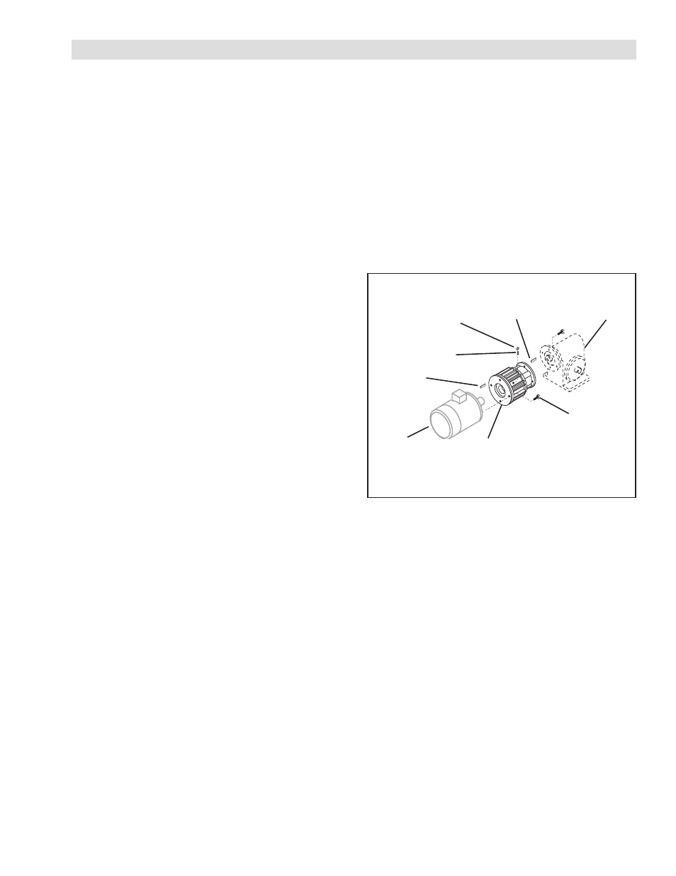
Key
(Item 25)
Motor
Customer
supplied key
Set Screw
(Item 26, 27, or 31)
Plug
(Item 27, 28, or 32)
Gear
Reducer
FIGURE 3
Socket Head Cap
Screw
and Lock Washer
(Items 29 and 30)
FMCBE
9. Insert and tighten the Set Screw and then install the
Plug (See Figure 3).
NOTE: On Model 625, the Set Screw is Item 26. On
Models 875 and 1125, the Set Screw is Item
31. On Model 1375, the Set Screw is Item
27.
On Model 625, the Plug is Item 27. On Models
875 and 1125, the Plug is Item 32. On Model
1375, the Plug is Item 28.
INSTALLATION