Nexen FMCBE-875 801428 User Manual
Page 13
13
FORM NO. L-20150-V-1112
MODELS 875, 1125, AND 1375 FEMALE PILOT
(continued)
12. Support the inner race of the new Ball Bearing (Item
2) and press the Drive Disc (Item 4) into the new Ball
Bearing (Item 2) and Female Pilot (Item 26) (See Figure
13).
13. Reinstall the Retaining Ring (Item 6) (See Figure 13).
14. Using the four Socket Head Cap Screws, secure the
Female Pilot (Item 26) to the Housing (Item 1) (See
Figure 13).
NOTE: On FMCBE Models 875 and 1125, the Socket Head
Cap Screws are Item 27. On FMCBE Model 1375,
the Socket Head Cap Screws are Item 13.
If you are replacing all the Ball Bearings and
O-ring Seals in the FMCBE, proceed with PARTS
REPLACEMENT—BEARINGS AND O-RING
SEALS; otherwise, proceed with next step.
15. Apply a drop of Loctite
®
242 to the threads of the four
Socket Head Cap Screws (Item 13) and secure the
two halves of the FMCBE together (See Figure 12).
16. Tighten the four Socket Head Cap Screws (Item
13) to the recommended torque (See Figure 12
and Table 3).
PARTS REPLACEMENT / PISTON, DRIVE DISC, BEARINGS, AND O-RING SEALS
ALL MODELS
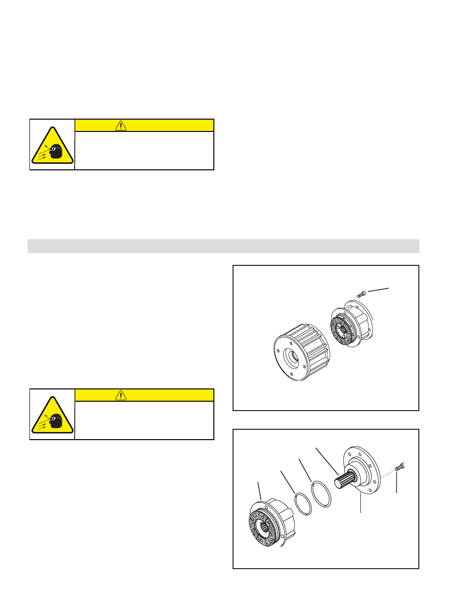
1. Remove the four Socket Head Cap Screws (Item 13)
and separate the two halves of the FMCBE (See Figure
14).
2. Remove the four remaining Socket Head Cap Screws
(Item 13) and slide the Male Pilot (Item 20), Stub Shaft
(Item 23), and the two Ball Bearings (Item 19) out of
the Air Chamber (Item 12) (See Figure 15).
3. Remove the old O-ring Seals (Items 21 and 22) from
the Male Pilot (Item 20) (See Figure 15).
4. Remove the Retaining Ring (Item 24) and press the
Stub Shaft (Item 23) out of the Male Pilot (Item 20)
(See Figure 16).
NOTE: The two old Ball Bearings (Item 19) are removed
from opposite ends of the Male Pilot (Item 20).
Do not remove the Retaining Rings (Item 18)
(See Figure 16).
5. Remove the two old Ball Bearings (Item 19) from the
Male Pilot (Item 20). One Ball Bearing will stay with
the Stub Shaft (Item 23) when pressed out (See Figure
16).
FIGURE 14
13
FIGURE 15
12
22
21
23
20
13
CAUTION
Working with spring loaded or tension
loaded fasteners and devices can cause
injury. Wear safety glasses and take the
appropriate safety precautions.
CAUTION
Working with spring loaded or tension
loaded fasteners and devices can cause
injury. Wear safety glasses and take the
appropriate safety precautions.