Nexen FMCBE-875 801428 User Manual
Page 14
14
FORM NO. L-20150-V-1112
PARTS REPLACEMENT / PISTON, DRIVE DISC,
BEARINGS, AND O-RING SEALS
(continued)
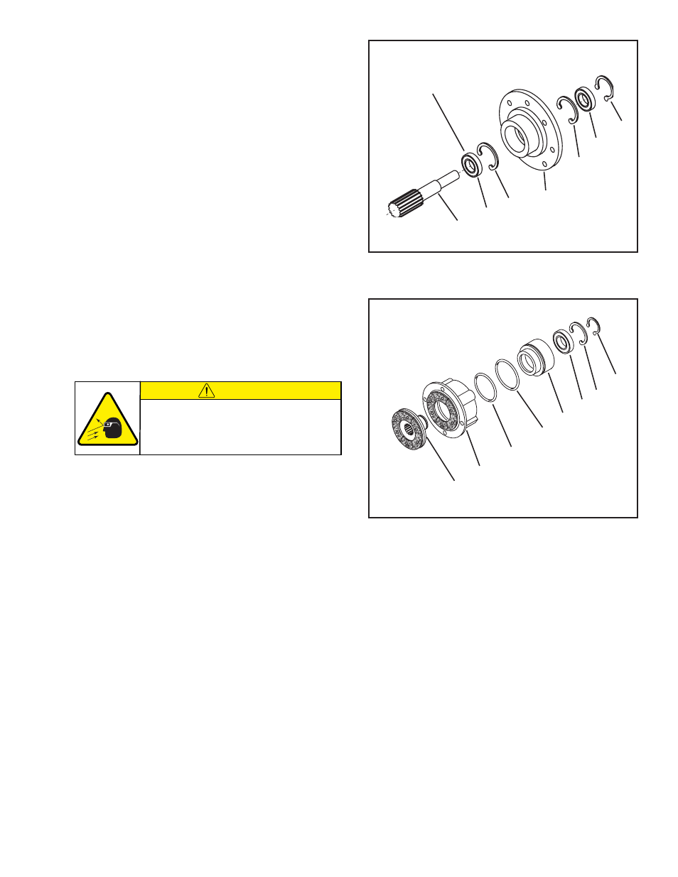
6. Clean the bearing bore of the Male Pilot (Item 20) with
fresh safety solvent, making sure all old Loctite
®
residue
is removed.
7. Press one new Ball Bearing (Item 19) onto the Stub
Shaft (Item 23) (See Figure 16).
8. Apply an adequate amount of Loctite
®
680 to evenly
coat the outer race of the new Ball Bearing (Item 19)
pressed onto the Stub Shaft (Item 23) and press the
new Ball Bearing and Stub Shaft into the Male Pilot
(Item 20) until the Ball Bearing is seated against the
Retaining Ring (Item 18) (See Figure 16).
9. Apply an adequate amount of Loctite
®
680 to evenly
coat the outer race of the second new Ball Bearing
(Item 19) and press it onto the Stub Shaft (Item 23) and
into the Male Pilot (Item 20) until it is seated against
the Retaining Ring (Item 18) (See Figure 16).
10. Reinstall the Retaining Ring (Item 24) (See Figure
16).
11. Remove the Retaining Ring (Item 6) and press the
Splined Disc (Item 9) out of the Air Chamber (Item 12)
(See Figure 17).
12. Slide the Piston (Item 16) out of the Air Chamber (Item
12) (See Figure 17).
13. Remove the O-ring Seals (Items 14 and 15) from the
Piston (Item 16) and the Air Chamber (Item 12) (See
Figure 17).
14. Remove the Retaining Ring (Item 3) from the Piston
(Item 16) (See Figure 17).
15. Press the old Ball Bearing (Item 2) out of the Piston
(Item 16) (See Figure 17).
16. Clean the bearing bore of the Piston (Item 16) with fresh
safety solvent, making sure all old Loctite
®
residue is
removed.
17. Apply an adequate amount of Loctite
®
680 to evenly
coat the outer race of the new Ball Bearing (Item 2);
then, press the new Ball Bearing (Item 2) into the Piston
(Item 16) and install the Retaining Ring (Item 3) (See
Figure 17).
FIGURE 16
23
19
18
20
18
19
24
Press this Ball Bearing on
first (See Step 7).
FIGURE 17
9
16
3
12
14
15
2
6
CAUTION
Working with spring loaded or tension
loaded fasteners and devices can cause
injury. Wear safety glasses and take the
appropriate safety precautions.
18. Lubricate the new O-ring Seals (Items 14 and 15)
and the contact surfaces on the Piston (Item 16) and
Air Chamber (Item 12) with a thin film of fresh O-ring
lubricant (See Figure 17).
19. Install the new O-ring Seals (Items 14 and 15) (See
Figure 17).
20. Slide the Piston (Item 16) back into the Air Chamber
(Item 12) (See Figure 17).
21. Support the inner race of the Ball Bearing (Item 2),
located inside the Piston (Item 16), and press the
Splined Disc (Item 9) into the Air Chamber (Item 12)
and Piston (Item 16) (See Figure 17).
22. Reinstall the Retaining Ring (Item 6) (See Figure 17).