Replacement parts, Parts replacement—input unit – Nexen FMCBE-875 801428 User Manual
Page 16
16
FORM NO. L-20150-V-1112
REPLACEMENT PARTS
The item or balloon number for all Nexen products is used
for part identification on all product parts lists, product
price lists, unit assembly drawings, bills of materials, and
instruction manuals.
When ordering replacement parts, specify model designation,
item number, part description, and quantity. Purchase
replacement parts through your local Nexen Distributor.
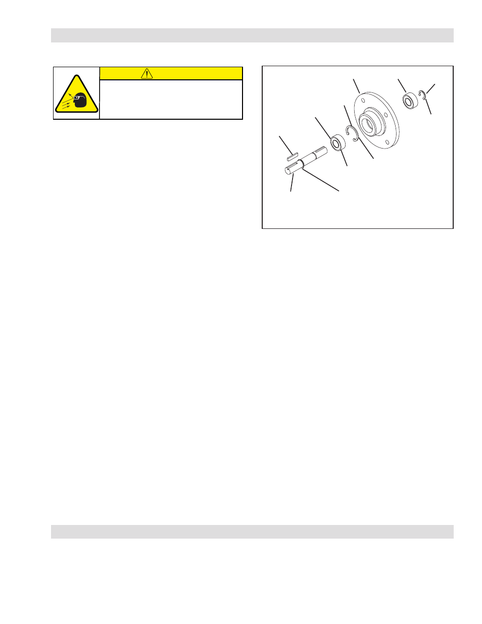
FIGURE 19
20
30
35
58
Do not
remove.
Remove
first.
Press this
Ball Bearing
onto the
Stub Shaft.
30
19
Do not remove Retaining
Ring (Item 35).
11
PARTS REPLACEMENT—INPUT UNIT
ALL MODELS
1. Remove the Retaining Ring (Item 35) from the output
end of the Input Unit (See Figure 19).
2. Press the Stub Shaft (Item 11) out of the Bearing
Flange (Item 20) (See Figure 19).
NOTE: One old Ball Bearing (Item 30) will come out
of the Bearing Flange (Item 20) with the Stub
Shaft (Item 11).
3. Press the first old Ball Bearing (Item 30) off the Stub
Shaft (Item 11) (See Figure 19).
4. Press the first new Ball Bearing (Item 30) onto the Stub
Shaft (Item 11) until it is seated against the Retaining
Ring (Item 35) (See Figure 19).
5. Press the second old Ball Bearing (Item 30) out of the
Bearing Flange (Item 20) (See Figure 19).
6. Clean the bearing bore of the Bearing Flange with fresh
safety solvent, making sure all old Loctite
®
residue is
removed (See Figure 19).
7. Apply an adequate amount of Loctite
®
680 to evenly
coat the outer race of the first new Ball Bearing (Item
30) on the Stub Shaft (Item 11) and press the first new
Ball Bearing and Stub Shaft into the Bearing Flange
(Item 20) until the Ball Bearing is seated against the
Retaining Ring (Item 58) (See Figure 19).
8. Apply an adequate amount of Loctite
®
680 to evenly
coat the outer race of the second new Ball Bearing
(Item 30) and press the second new Ball Bearing onto
the Stub Shaft and into the Bearing Flange (Item 20)
until the Ball Bearing is seated against the Retaining
Ring (Item 58) (See Figure 19).
9. Reinstall the Retaining Ring (Item 35) (See Figure
19).
CAUTION
Working with spring loaded or tension
loaded fasteners and devices can cause
injury. Wear safety glasses and take the
appropriate safety precautions.