Setup – Nexen Smart Valve 964508 User Manual
Page 8
5
FORM NO. L-20353-C-0302
SETUP
Digital Pressure Selection - Jumper and Switch Settings (See Figure 6)
Jumper W1
ON
Jumper W2
DIG
Jumper W3
NORM, alarm output transistor turns on during an alarm
REV, alarm output transistor turns off during an alarm
Mode Switch
Select “0-2”, see Table 1.
NOTE: Table 1 displays the standard mode switch settings "0-2". Mode switch settings “3-7” are reserved for custom
pressure tables. Contact Nexen (1-800-843-7445) if you require a custom table for your application.
Analog Pressure Selection - Jumper and Switch Settings (See Figure 6)
Jumper W1
ON
Jumper W2
ANA
Jumper W3
NORM, alarm output transistor turns on during an alarm
REV, alarm output transistor turns off during an alarm
Mode Switch
Select “F”
Maintain Pressure Function - Jumper and Switch Settings (See Figure 6)
Jumper W1
ON
Jumper W2
DIG
Jumper W3
NORM, alarm output transistor turns on during an alarm
REV, alarm output transistor turns off during an alarm
Mode Switch
Select “E”
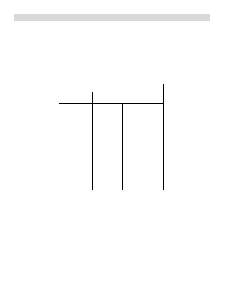
TABLE 1 DIGITAL PRESSURE SELECTION MODE
off
off
off
off
off
off
off
on
off
off
on
off
off
off
on
on
off
on
off
off
off
on
off
on
off
on
on
off
off
on
on
on
on
off
off
off
on
off
off
on
on
off
on
off
on
off
on
on
on
on
off
off
on
on
off
on
on
on
on
off
on
on
on
on
Pressure (psig)
0
1
2
3
4
5
6
7
8
9
10
11
12
13
14
15
hold
0
hold
0
5
0
6
10
20
12
15
24
18
20
28
24
25
30
30
30
34
36
35
38
42
40
40
48
45
44
54
50
48
60
55
50
66
60
54
72
65
58
78
70
70
84
75
80
Mode Switch
0
1
2
Pressure Select Inputs
3
2
1
0
Pressure Selection
Value