Electrical connections, Caution – Nexen Smart Valve 964508 User Manual
Page 6
3
FORM NO. L-20353-C-0302
Wire Color
+24V DC
DC Common
Exhaust Pressure Input
Signal Input
Alarm Output (+)
Alarm Output (-)
Function
Pressure Select 3
Pressure Select 2
Pressure Select 1
Pressure Select 0
Pressure Select
Pressure Select 0 also serves as the analog pressure select input.
Common
*
*
RED
BLACK
WHITE
GREEN
BROWN
BLUE
ORANGE
YELLOW
PURPLE
GRAY
PINK
A
A
B
B
C
C
D
D
E
E
F
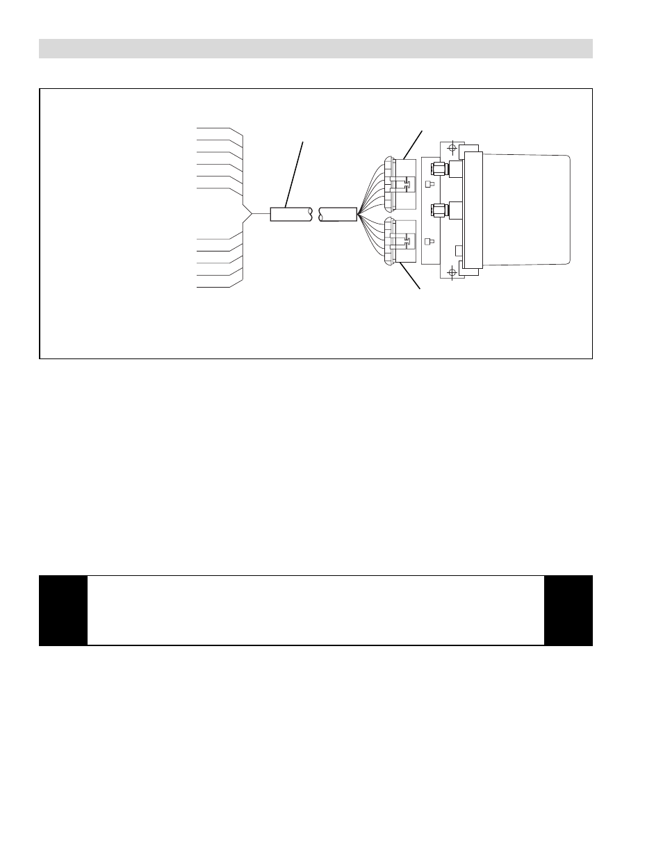
ELECTRICAL CONNECTIONS
Power/Signal
Cable
6 Pin Connector
5 Pin Connector
FIGURE 3 SMARTVALVE ELECTRICAL CONNECTIONS
+24 VDC & DC Common: The SmartValve requires 24VDC to operate; refer to the SPECIFICATIONS section for
current rating.
Exhaust Pressure Input: Normally 12-24 VDC is present at this input, at any time the voltage is removed the
SmartValve will respond by exhausting all air pressure and provide an alarm signal. This input uses the same DC
Common as the + 24 VDC power supply. A yellow indicator D9 on the SmartValve printed circuit board will be on
when 24 VDC is present at this input.
Alarm Output: This output is an optically isolated relay that is activated upon a torque overload. The action of the relay
is controlled by jumper W3. When W3 is set to NORMAL, the relay will conduct current during an alarm event and
when set to "REVERSE", the relay will block current during an alarm event. Voltage and current ratings of the relay are
listed in the SPECIFICATIONS section.
CAUTION
The alarm output transistor will only conduct current in one direction. Observe the
proper polarity per Figure 3.