Nexen Smart Valve 964508 User Manual
Page 7
4
FORM NO. L-20353-C-0302
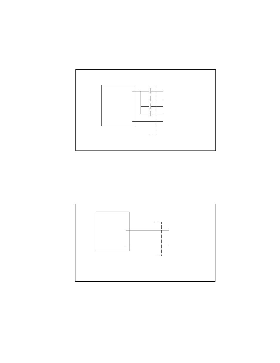
Pressure Select Inputs: These inputs allow users to select one of sixteen pressures depending on the input sequence,
refer to the OPERATION section for more details. The inputs will accept a 12-24VDC signal and are optically isolated.
An input is selected by applying 12-24 VDC and deselected by removing the voltage. The Pressure Select Common is
independent of the +24VDC power supply common and facilitates connecting these inputs to another controller (i.e.
PLC or computer) that has a different power supply than the SmartValve. Yellow indicators marked “0", "1", "2", "3” on
the SmartValve printed circuit board will turn on when 12-24VDC is present at the corresponding input. Refer to the
SPECIFICATIONS section for the current requirement of these inputs. Figure 4 shows the pressure select input
connections.
FIGURE 4 PRESSURE SELECT INPUT CONNECTIONS
Analog Pressure Selection Input: An analog signal can be used to select pressures through the Pressure Select "0"
input. The SmartValve will convert the 0-10VDC input to a 0-80 psig output Figure 5 displays the analog pressure
select input connections.
FIGURE 5 ANALOG PRESSURE SELECT INPUTS
Optional Isolated
Power Supply
User Supplied
SmartValve Wires
_
+
12-24VDC
DC Common
Orange
Purple
Gray
Yellow
Pink
Gray
Analog Output
(0-10VDC)
User Supplied
SmartValve Wires
*Analog Common
Customer
Supplied PLC
_
+
Pink
*Connect the analog common to the
SmartValve’s DC common