Nexen T-450 819001 User Manual
Page 9
9
FORM NO. L-20071-R-1211
PARTS REPLACEMENT
FRICTION FACINGS
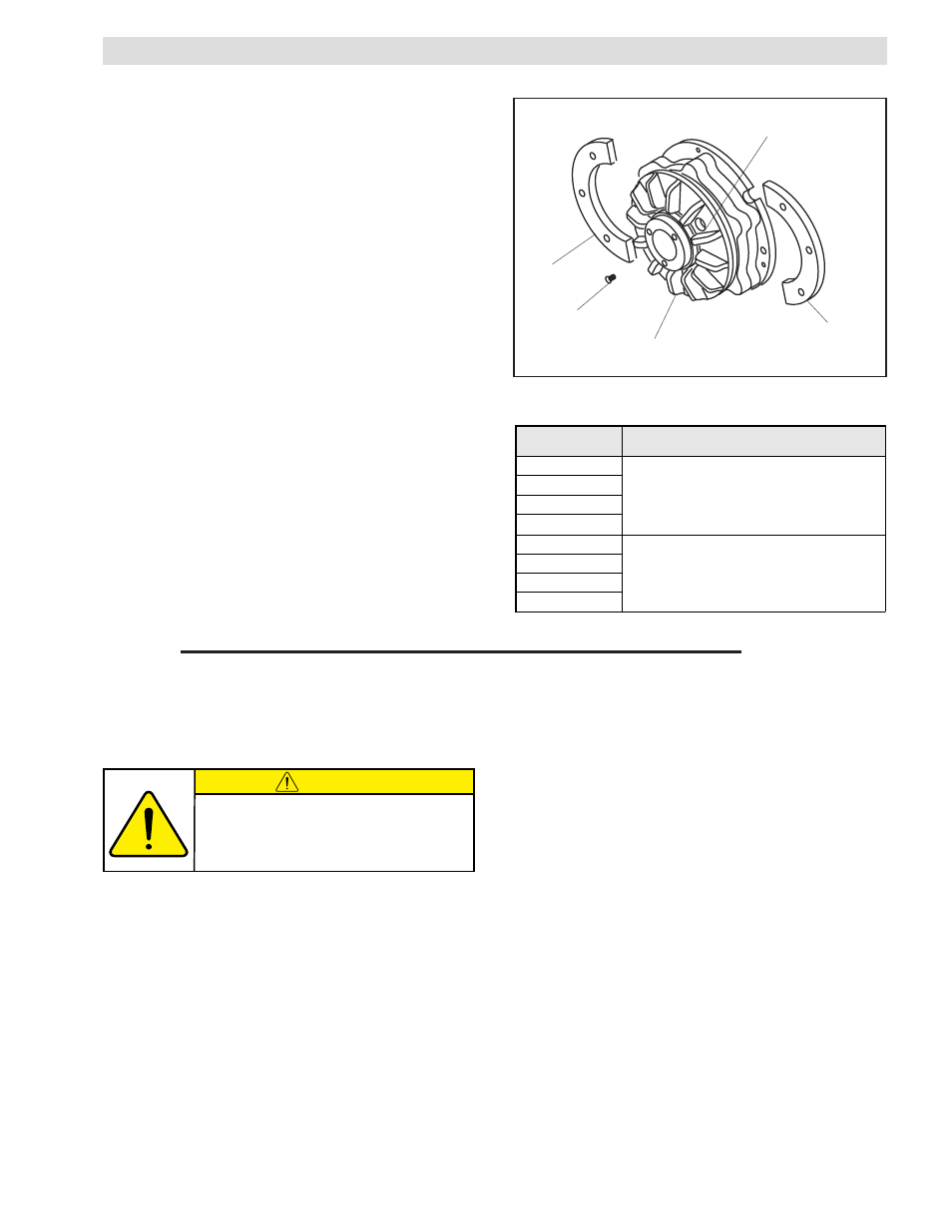
NOTE: Refer to Figure 5.
1. Align the holes in the Friction Disc Hub (Item 1) with
the Machine Screws (Item 14) holding the split Friction
Facing (Item 5).
2. Remove the old Machine Screws (Item 14).
3. Remove the old split Friction Facings (Item 5).
4. Install the new split Friction Facings (Item 5).
5. Secure the new split Friction Facings (Item 5) using the
new Machine Screws with locking patch (Item 14).
6. Tighten the new Machine Screws to the recommended
torque (See Table 4).
FIGURE 5
Align holes
with Machine
Screws.
Item 5
Item 14
Item 1
Item 5
TABLE 4
Model
Tightening Torques
T-450
19 in-lb [2.1 Nm]
T-450A
T-600
T-600A
T-800
60 in-lb [6.8 Nm]
T-800A
T-1000
T-1000A
BEARING AND 0-RING SEALS
5. Alternately and evenly remove the three old Shoulder
Bolts (Item 6) and Compression Springs (Item 7).
6. Separate the Piston Plate (Item 3) and split Friction
Facing (Item 5) from the Air Chamber (Item 4).
7. Remove the Piston (Item 2) from the Air Chamber (Item
4).
1. Remove the Retaining Ring (Item 9).
2. Press the Friction Disc Hub (Item 1) out of the Ball
Bearing (Item 8).
3. Remove the Retaining Ring (Item 10).
4. Press the old Ball Bearing (Item 8) out of the Air
Chamber (Item 4).
NOTE: Refer to Figure 6.
CAUTION
Working with spring or tension loaded
fasteners and devices can cause injury.
Wear safety glasses and take the
appropriate safety precautions.
- T-450 819005 T-450 819000 T-450 819007 T-600 820607 T-600 820601 T-600 820600 T-800 824200 T-800 824212 T-800 824207 T-800 824201 T-800 824204 T-1000 824301 T-1000 824300 T-1000 824309 T-1000 824307 T-450 818910 S-450 818910 T-600A 820503 S-600A 820503 T-600 820510 S-600 820510 T-800A 827402 S-800A 827402 T-800 827410 S-800 827410 T-1000A 827502 S-1000A 827502 T-800 827401 S-800 827401 T-1000 827501 S-1000 827501 T-450 818901 S-450 818901 T-600 820501 S-600 820501 T-450 818904 S-450 818904 T-800 827400 S-800 827400 T-450 818900 S-450 818900 T-450A 818903 S-450A 818903 T-1000 827500 S-1000 827500 T-600 820500 S-600 820500 T-1000 827510 S-1000 827510 T-450A 819006 T-450A 819004 T-450A 819003 T-600A 820606 T-600A 820605 T-600A 820604 T-800A 824202 T-800A 824205 T-800A 824203 T-1000A 824308 T-1000A 824306 T-1000A 824305