Installation, Brake guard installation – Nexen T-450 819001 User Manual
Page 5
5
FORM NO. L-20071-R-1211
CAUTION
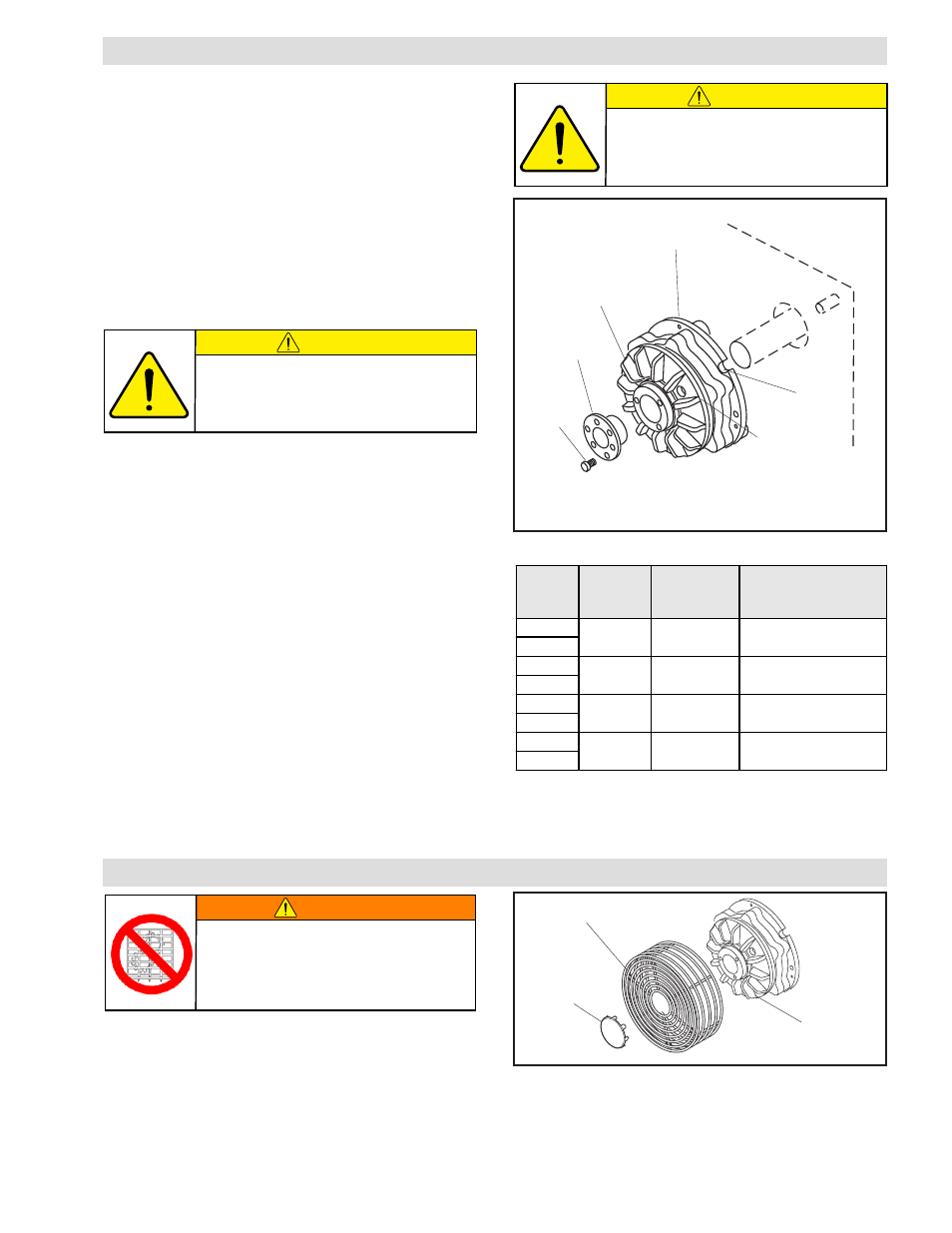
FIGURE 1
Friction Disk
Hub
(Item 1)
INSTALLATION
NOTE: Refer to Figure 1.
Q.D.
Bushing
Pull-Up
Bolts
Air Chamber
(Item 4)
Torque
Pin Slot
Check runout
with Dial
Indicator on
Friction Disc Hub
(Item 1).
TABLE 1
1. Remove any dirt, grease, or foreign material from the
Friction Disc Hub (Item 1) bore and the tapered surfaces
of the Q.D. Bushing.
NOTE: Do not use lubricants when installing Q.D.
Bushing.
NOTE: Do not strike Q.D. Bushing to force it into the bore
of the Friction Disc Hub.
2. Slide Q.D. Bushing into the bore of the Friction Disc Hub
(Item 1).
Model
Bushing
Type
Maximum
Bore*
Pull-Up Bolt
Tightening Torque
T-450
JA
1.000 in
5.0 ft-lbs [6.7 Nm]
T-450A
T-600
SH
1.375 in
10.0 ft-lbs [13.5 Nm]
T-600A
T-800
SK
2.125 in
15.0 ft-lbs [20.2 Nm]
T-800A
T-1000
E
2.750 in
60.0 ft-lbs [81.0 Nm]
T-1000A
*Standard depthKeyway
3. Insert cap screws into Q.D. Bushing, aligning them with
the tapped holes in the Friction Disc Hub (Item 1).
4. Position Brake on the shaft.
NOTE: There should be an 1/8 - 1/4" gap between the
Q.D. Bushing flange and the Friction Disc Hub after the
cap screws have been tightened to the recommended
torque.
Runout is minimized if a Dial Indicator is used as the Q.D.
Bushing cap screws are tightened. Place contact tip of
Dial Indicator on smooth surface of the Friction Disc Hub
(Item 1) to measure runout. Runout on this surface must
not exceed 0.005 TIR when cap screws are tightened.
5. Alternately and evenly tighten Q.D. Bushing cap screws
to torque recommended in Table 1.
NOTE: Keep torque pin as short as possible.
Do not install bolts into the threaded
holes of the Q.D. Bushing. The threaded
holes in the Q.D. Bushing are only used
for removal of the Q. D. Bushing.
CAUTION
Do not flange mount T-Brakes. Bearing
preload will result after bushing is installed
and premature bearing failure will ensure.
FIGURE 2
Brake Guard
End Cap
T Brake
Air Chamber
BRAKE GUARD INSTALLATION
NOTE: Refer to Figure 2.
1. Align the mounting holes of the Brake Guard with the
four tapped holes in the brake Air Chamber.
2. Using the four 10-24 X 1/2 Phillips Head Pan Screws,
secure the Brake Guard to the T Brake. Tighten screws
to 35 in-lbs [4 Nm].
6. Secure the Air Chamber (Item 4) to prevent rotation and
take up brake torque. A torque pin slot is provided in the
Air Chamber.
WARNING
Ensure proper guarding of the product is
used. Nexen recommends the machine
builder design guarding in compliance
with OSHA 29 CFR 1910 “Occupational
Safety and Health Hazards”.
3. If the Brake Guard is shipped with an End Cap, place
the End Cap over the front of the Brake Guard and bend
the tabs around the Brake Guard to hold the End Cap
in place.
- T-450 819005 T-450 819000 T-450 819007 T-600 820607 T-600 820601 T-600 820600 T-800 824200 T-800 824212 T-800 824207 T-800 824201 T-800 824204 T-1000 824301 T-1000 824300 T-1000 824309 T-1000 824307 T-450 818910 S-450 818910 T-600A 820503 S-600A 820503 T-600 820510 S-600 820510 T-800A 827402 S-800A 827402 T-800 827410 S-800 827410 T-1000A 827502 S-1000A 827502 T-800 827401 S-800 827401 T-1000 827501 S-1000 827501 T-450 818901 S-450 818901 T-600 820501 S-600 820501 T-450 818904 S-450 818904 T-800 827400 S-800 827400 T-450 818900 S-450 818900 T-450A 818903 S-450A 818903 T-1000 827500 S-1000 827500 T-600 820500 S-600 820500 T-1000 827510 S-1000 827510 T-450A 819006 T-450A 819004 T-450A 819003 T-600A 820606 T-600A 820605 T-600A 820604 T-800A 824202 T-800A 824205 T-800A 824203 T-1000A 824308 T-1000A 824306 T-1000A 824305