Nexen T-450 819001 User Manual
Page 6
6
FORM NO. L-20071-R-1211
AIR CONNECTIONS
NOTE
Nexen pneumatically actuated devices require clean, pressure regulated air for maximum performance and
life. All seals in Nexen pneumatically operated devices are lubricated for life, and do not require additional
lubrication.
However, some customers prefer to use an air line lubricator, which injects oil into the pressurized air,
forcing an oil mist into the air chamber. This is acceptable, but care must be taken to ensure once an air mist
lubrication system is used, it is continually used over the life of the product as the oil mist may wash free the
factory installed lubrication.
Locate the lubricator above and within ten feet of the product, and use low viscosity oil such as SAE-10.
Synthetic lubricants are not recommended.
Nexen product's bearings are shielded and pre-lubricated, and require no further lubrication.
LUBRICATOR DRIP RATE SETTINGS
1. Close and disconnect the air line from the unit.
2. Turn the Lubricator Adjustment Knob counterclockwise three
complete turns.
3. Open the air line.
4. Close the air line to the unit when a drop of oil forms in the
Lubricator Sight Gage.
5. Connect the air line to the unit.
6. Turn the Lubricator Adjustment Knob clockwise until
closed.
7. Turn the Lubricator Adjustment Knob counterclockwise one-
third turn.
8. Open the air line to the unit.
LUBRICATION
CAUTION
These settings are for Nexen supplied
lubricators. If you are not using a Nexen
lubricator, calibration must follow the
manufacturer's suggested procedure.
CAUTION
Low air pressure will cause slippage and
overheating. Excessive air pressure will
cause abrupt starts and stops, reducing
product life.
All Nexen pneumatically actuated devices require clean
and dry air, which meet or exceeds ISO 8573.1:2001
Class 4.4.3 quality.
NOTE
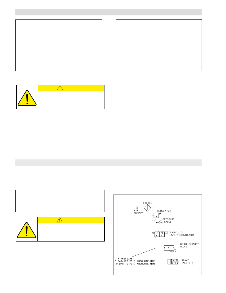
For quick response, Nexen recommends a quick exhaust
valve and short air lines between the Control Valves and
the unit. Align the air inlet ports to a down position to
allow condensation to drain out of the air chambers of
the product.
The following is a common air supply scheme used with
this product. This is an example and not an all-inclusive
list. All air circuits to be used with this product must be
designed following EN983 guidelines.
- T-450 819005 T-450 819000 T-450 819007 T-600 820607 T-600 820601 T-600 820600 T-800 824200 T-800 824212 T-800 824207 T-800 824201 T-800 824204 T-1000 824301 T-1000 824300 T-1000 824309 T-1000 824307 T-450 818910 S-450 818910 T-600A 820503 S-600A 820503 T-600 820510 S-600 820510 T-800A 827402 S-800A 827402 T-800 827410 S-800 827410 T-1000A 827502 S-1000A 827502 T-800 827401 S-800 827401 T-1000 827501 S-1000 827501 T-450 818901 S-450 818901 T-600 820501 S-600 820501 T-450 818904 S-450 818904 T-800 827400 S-800 827400 T-450 818900 S-450 818900 T-450A 818903 S-450A 818903 T-1000 827500 S-1000 827500 T-600 820500 S-600 820500 T-1000 827510 S-1000 827510 T-450A 819006 T-450A 819004 T-450A 819003 T-600A 820606 T-600A 820605 T-600A 820604 T-800A 824202 T-800A 824205 T-800A 824203 T-1000A 824308 T-1000A 824306 T-1000A 824305