Tam-rail, Post mount & post sleeve installation instructions, Post kit includes – TAMKO TAM-RAIL User Manual
Page 3: Post sleeve installation instructions, Installation instructions for masonry application
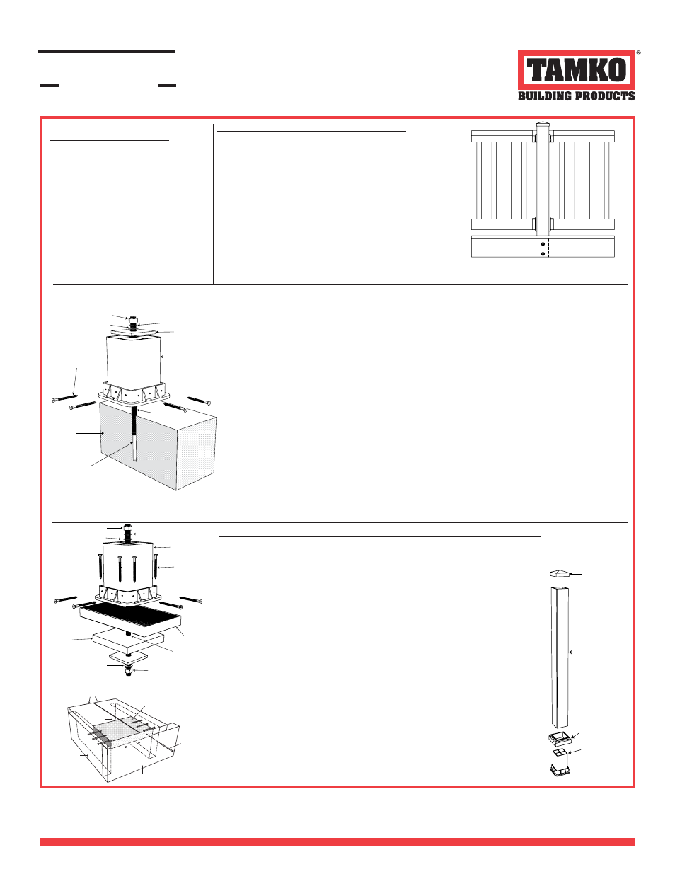
Post Mount & Post Sleeve
Installation Instructions
Post Kit Includes:
(1 ea.) 4” x 4” x 38” Post Sleeve
(1 ea.) Structural Post Mount
(1 ea.) 4” New England Post Ring
(1 ea.) 4” Pyramid Post Cap
(1 ea.) 1/2” x 12” Threaded Rod
(2 ea.) 1/2” Washer
(1 ea.) 1/2” Lock Washer
(2 ea.) 1/2” Hex Nut
(16 ea.) 2 1/2” Stainless Screws
(1 ea.) 3” x 3” Square Plate with 1/2” hole
(1 ea.) #3 Square Drive Bit
(1 ea.) HVU Epoxy Capsule
Post Sleeve Installation Instructions
A 4” x 4” Post Sleeve can be installed over a 4” x 4” nominal wooden
post consisting of pressure treated #2 Southern Yellow Pine or better.
The wooden post shall be attached inside the rim joist utilizing two 1/2”
diameter carriage bolts installed along the center line of the post located
at 1 3/4” and 5 3/4” from the top of the fl oor surface with minimum
distance of 1 3/4” from the lowest installed carriage bolt to the bottom of
the post. The rim joist shall be a minimum of 7 1/4” deep.
1. To install the TAM-RAIL Post Sleeve, fi rst review the installation of the
structural wood post. Consult your building professional to ensure selec-
tion of fasteners is compatible with your joist and substructure material.
2. Slide the TAM-RAIL Post Sleeve over the 4x4 wood post.
3. Slide the Post Ring down the Post Sleeve.
4. Attach the Post Cap to the Post Sleeve with PVC glue. (Not provided)
Pyramid Post Cap
Post Sleeve
New England
Post Ring
Post Mount
f
f
f
-LJM;LMJ9D
=;C
f
f
f
DG;CAF?
%#(!
$)#-.
$)#-.
,#'
(#&-
f
$)#-.
Installation Instructions for Wood Deck Application
(Tools Required: Drill, 1/2” drill bit, #3 Square drive bit, level, wrench)
1. Make sure the area under the mounting location has an additional 2” x 8” block (not
included in Post Mount Kit) fastened using 3 fasteners on each side through the joists
directly under the deck surface. (See Joist Mount Diagram)
2. Drill a 1/2” hole through the wood surface and joist block located at the center of your
post location.
3. Align center hole on post mount with hole in surface. Insert threaded rod with (1) 1/2”
washer, (1) 1/2” lock washer and (1) 1/2” hex nut on the top. (In that order)
4. Slide the 3” square plate onto the bolt under the mounting surface followed by (1)
1/2” washer and (1) 1/2” hex nut on the bolt leaving approximately 1” of threaded rod
beyond the end of the hex nut.
5. Tighten hex nut from the top until post mount is secure.
6. Secure the post mount to the deck surface using (2) of the provided 2 1/2” stainless
steel screws on each side of the post mount in the predrilled holes.
7. Insert post into post mount and level vertically.
NOTE: DO NOT SUBSTITUTE ANY POST SLEEVE FOR THE ONE PROVIDED IN
THE KIT.
8. Secure post sleeve in post mount using (2) of the included 2 1/2” stainless screws on
each side of the post mount. Indentions on each side of the post mount mark the cor-
rect location for each screw. Leave the middle indention unused. It may be necessary to
drill 1/8” pilot holes.
9. Slide the post ring down the post sleeve and over post mount.
10. Attach post cap to post sleeve with PVC glue. (Not provided)
(For use with all TAM-RAIL 6ʼ Railing Kits)
f
f
f
f
-LJM;LMJ9D
f
"0/
'9KGFJQ
Please check the local building codes for proper
post installation. If additional questions arise,
consult your local building code offi cial.
Installation Instructions for Masonry Application
(Tools Required: Hammer drill with 9/16” masonry bit, drill, #3 Square drive bit, level, wrench, 3/4” socket, mallet)
(For use with all TAM-RAIL 6ʼ Railing Kits)
1. Determine the mounting location for the center of the post mount and hammer drill a 9/16” hole 4 1/4” deep for the
provided epoxy capsule. Clean dust out of hole before inserting epoxy capsule. Place unopened epoxy capsule
into hole.
2. Thread the (1) 1/2” hex nut, (1) 1/2” washer and (1) 1/2” hex nut onto fl at end of threaded rod. Tighten together the
two 1/2” hex nuts securing the washer between them. The top nut should be fl ush with the top of the threaded rod.
Insert a square drive shaft into the rotary hammer drill and attach the 3/4” socket. At the rotary hammer drill setting,
place 3/4” socket on the top hex nut and drive rod into the hole and down through the epoxy capsule. (An adjustable
wench will work as well.) Note: The Hilti H.A.S rod should be screwed to a maximum tightening torque of 30
ft-pounds. The base material thickness should be a minimum 6 1/4”. Stop drill rotation immediately upon reach-
ing bottom of hole. (Threaded rod will mix with epoxy for full set. Curing times: 20 minutes for temperatures above
68º F, 30 minutes for temperatures between 50º - 68º F, 1 hour for temperatures between 32º - 50º F, and 5 hours for
temperatures between 23º - 32º F.)
3. After the appropriate time, as noted above, has elapsed, remove the (2) 1/2” hex nuts and (1) 1/2” washer and
slide the post mount into position on the threaded rod.
4. Place 3” square plate, (1) 1/2” washer, (1) 1/2” lock washer (in that order) onto the threaded rod and secure the
post mount by tightening down with (1) 1/2” hex nut.
5. Insert post into post mount and level vertically. NOTE: DO NOT SUBSTITUTE ANY POST SLEEVE FOR THE
ONE PROVIDED IN THE KIT.
6. Secure post in post mount using (2) of the included 2 1/2” stainless screws on each side of the post mount. Inden-
tions on each side of the post mount mark the correct location for each screw. Leave the middle indention unused. It
may be necessary to drill 1/8” pilot holes.
7. Slide the post ring down the post sleeve and over post mount.
8. Attach post cap to post sleeve with PVC glue. (Not provided)
For assistance, information regarding, or to receive a
copy of TAMKO’s Limited Warranty, contact us at
1-800-641-4691 or visit us online at tamko.com.
It is the responsibility of the installer to meet all building code and safety requirements and to obtain all
required building permits. These instructions are only a guide and may not address every circumstance.
TAMKO Building Products Inc. shall not be held liable for improper or unsafe installations. These
application instructions were current at the time of printing. To obtain a copy of the most current version of
the application instructions, visit us online at tamrail.com or call us at 1-800-641-4691.
RAILING SYSTEMS
TAM-RAIL
®