Charge air cooler installation, cont’d – Vortech 1997-2004 C5 Corvette User Manual
Page 27
P/N: 4GR020-010 v1.7, 2009-11-25
©2009 Vortech Engineering, LLC
All Rights Reserved, Intl. Copr. Secured
15
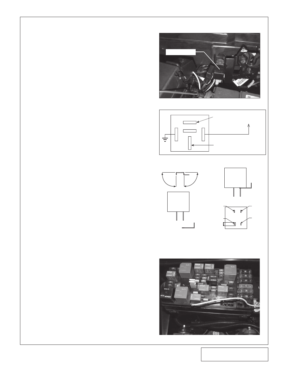
13. CHARGE AIR COOLER INSTALLATION, cont’d
RELAY
(+)BATTERY TERMINAL
(+)TERMINAL ON
WATER PUMP
GROUND
87
87A
86
85
30
TERMINAL #87 ON
FACTORY FUEL
PUMP RELAY
Fig. 13-e
Fig. 13-d
SUPPLiEd RELAY
12. Connect the supplied long red wire to
the water pump power wire using a
female slide connector. Route the water
pump power wire up to and across the
cowl below the windshield and secure
using zip ties
B. Water pump wiring
1. Drill out the relay mounting hole to 1/4"
and mount the supplied relay using the
forward most screw on the passenger
side hood latch. (See Fig 13-d.)
2. Connect the water pump power wire up
to the relay terminal #87.
3. Using the supplied ring terminal connec-
tor, run the relay ground wire from termi-
nal #86 down to the ground terminal
located on top of the vehicle frame
below the battery.
4. Connect the supplied fuse holder from
the #30 relay terminal to the remote (+)
positive battery terminal on the fuse box
using a female slide connector and a
large ring terminal connector.
5. Using the yellow wire, connect relay ter-
minal #85 to the factory fuel pump relay
terminal #87 in the fuse box using the
supplied mini fuse tap and slide connec-
tor. (See Figs 13-e, 13-f, 13-g.)
C. Surge tank install
1. The surge tank will be installed just
behind the power steering reservoir on
the same bracket.
2. Connect a length of the supplied hose to
the 90° fitting installed in the bottom of
the supplied surge tank and point
towards the rear of the vehicle. Install
and tighten a plastic clamp.
3. Install another 90 degree fitting into the
surge tank opposite the two 1/4-20
mounting inserts. Point this fitting
towards the front of the vehicle. Attach
the supplied hose to this fitting with a
clamp.
4. Install the surge tank onto the bracket
using the supplied 1/4-20 screws. The
bracket may need to be loosened from
the head in order to install the surge
tank. (See Fig. 11-a.)
5. Route the hose attached to the bottom
of the surge tank to the 90° fitting
installed in the top of the reservoir.
Secure with a clamp.
6. Re-install the vehicle splash guard.
Fig. 13-f
Fig. 13-g
86
85
87
30
FACTORY
FUEL
PUMP
RELAY
FUSE TAP
MODIFICATION
BEND UP 90
° BEND UP 90°
FACTORY
FUEL
PUMP
RELAY
MODIFIED
FUSE TAP
INSTALLED MODIFIED
FUSE TAP
BOTTOM VIEW
SIDE VIEW