Vortech Universal Small Block Chevy Carbureted User Manual
Page 23
P/N: 4GP020-015 v3.0, 2012-03-26
©2012 Vortech Engineering, Inc.
All Rights Reserved, Intl. Copr. Secured
13
6.2 dISCHARGE dUCTING/CARBURETOR HAT (ENTRY LEVEL V3 KITS)
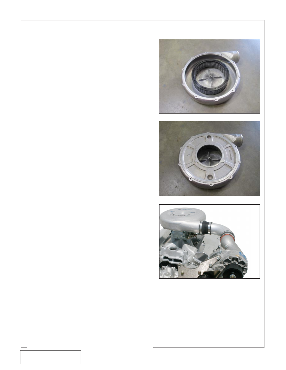
A. Locate the 8M106-011 carb hat assembly.
B. Place the carb hat housing bottom side up on
a non-marring surface.
C. Place the diffuser onto the receiver groove
machined into the carb hat housing. (See Fig.
6.2-a)
D. Place the carb hat base onto the housing,
making sure the diffuser seats into the base's
machined groove. Orient approximately as
shown. (See Fig. 6.2-b)
E.
Install the ten (10) retaining clips around the
circumference with the included 1/4-20
screws. Do not tighten at this time, so the
base can rotate within the hat.
F.
Temporarily place the assembly onto the car-
buretor so the float adjustment screws are
centered within the reliefs on the base and
the inlet points to the driver side.
G. Locate the 4GP112-050 discharge assembly.
Temporarily place the 90° aluminum elbow
between the supercharger discharge and the
carb hat inlet. Adjust the clocking of the carb
hat relative to the base as needed for proper
alignment. Snug one or two of the retaining
clips to secure the base to the hat.
H. Remove the hat assembly from the engine
and secure the remaining retaining clips.
I.
Place the included gasket onto the carbure-
tor's air cleaner mounting surface. Place the
hat assembly into position and secure to the
carburetor with the included 5/16-18 screw
and gasket sealing washer.
J.
Install the 90° aluminum elbow between the
supercharger discharge and the carb hat
inlet. Couple to the discharge with the
Ø2.75" silicone sleeve and two (2) #44 worm
gear clamps. Couple to the carb hat inlet
with the Ø2.75" x Ø3.0" stepped coupler, one
(1) #44 worm gear clamp, and one (1) #48
worm gear clamp. (See Fig. 6.2-c)
K. Compressor Bypass Valve Placement:
Vortech suggests attaching the compressor
bypass valve (bypass valve and mounting
flange are not included) onto the supercharg-
er discharge tube. After all of the major kit
components have been installed, mock-up
the bypass valve and flange so that proper
clearance to vehicle hood and surrounding
components is confirmed. Actual valve loca-
tion will vary depending on the specific appli-
cation. After the bypass flange and valve are
permanently mounted, connect the bypass
valve vacuum port to a proper vacuum
source on the engine.
Fig. 6.2-a
Fig. 6.2-b
Fig. 6.2-c