Vortech Universal Small Block Chevy Carbureted User Manual
Page 20
P/N: 4GP020-015 v3.0, 2012-03-26
©2012 Vortech Engineering, Inc.
All Rights Reserved, Intl. Copr. Secured
10
A. Locate the supercharger drive assembly
(4GP116-041). Using the 7/16-20 x 2.75"
screw and washer, loosely install the appropri-
ate spacer for your application to the front of
the factory crank pulley.
B. Rotate the previously installed crank pulley
spacer to align the three mounting holes. Install
the supplied supercharger crank pulley and
secure using the supplied hardware. (3/8-24 x
5" for Serpentine and 3/8-24 x 4.75" for V-belt
applications.) Torque center bolt to 35 ft.lbs.
and the three pulley retainers to 25 ft.lbs.
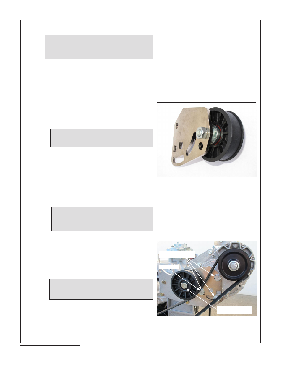
F.
Loosely install the belt tensioner
assembly onto the supercharger
using the M12 hardware provided.
Locate the supplied supercharger
drive belt and install between the
crank pulley and supercharger pul-
ley. Using a 1/2" ratchet, apply
tension to the supercharger drive
belt and secure the three M12
screws previously installed. (See
Fig. 5-a, 5-b, 5-c.)
5. CRANK PULLEY ANd SUPERCHARGER dRIVE PULLEY INSTALLATION
NOTE: If the supercharger drive pulley will not slide
onto the shaft DO NOT FORCE IT. Light
heating of the supercharger drive pulley with
a propane torch will aid in installation.
NOTE: Take care to ensure that all pulleys and spac-
er are piloting correctly and seated flat against
their mounting faces.
NOTE: Two crank pulley spacers are provided in this
system. 4GP017-031 (3.695" long) is to be used
for serpentine drive systems. The 4GP017-041
(3.293" long) is to be used for V-belt applications.
NOTE: The bearing retaining ring on the pulley should
be facing the pulley spacer to properly clear
the “thick” retaining washer. (See Fig. 6-d.)
C. Install all applicable accessory belts at this time
and tension using the appropriate belt tension-
er for your application.
D. (10-Rib Units Only) Lightly grease the super-
charger input shaft and/or the supercharger
drive pulley bore. Install the pulley onto the
supercharger input shaft and rotate the pulley
to align the keyways. Slide the square key into
the keyway. Install the pulley retainer assembly
into the input shaft and hand tighten.
Fig. 5-a: Entry Level V3 6-Rib Application
Fig. 5-b: Entry Level V3 6-Rib Application
M12-1.75 X 50mm
SCREW
"LOW" HEAD
M12-1.75 X 20mm
SCREWS
E.
Locate the manual tensioner assembly:
1. 10-Rib Applications (4GP111-041):
Install the 7/16-20 screw through the
7/16" “thick” washer, tensioner pulley,
pulley spacer and tensioner plate.
Secure using the 7/16"SAE washer
(thinner one) and Nyloc nut provided.
2. 6-Rib Applications (4FA111-032):
Install the M12 x 50mm screw through
the steel dust shield, tensioner pulley,
large diameter pulley spacer, small pul-
ley spacer, and then through the ten-
sioner plate. Secure the assembly
using the M12 nut.