Vortech Universal Small Block Chevy Carbureted User Manual
Page 17
P/N: 4GP020-015, v3.0, 2012-03-26
©2012 Vortech Engineering, Inc.
All Rights Reserved, Intl. Copr. Secured
7
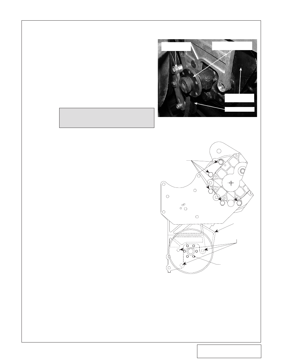
NOTE:
The end of the pump shaft should
be flush with the end of the drive
flange when fully installed.
2. Mount the power steering pump to the
back side of the cast bracket using the
supplied 3/8-16 flat-head screws. Locate
the power steering pump drive flange.
Using the appropriate GM power steering
pulley installer, install the drive flange as
you would a normal power steering pulley.
(See Fig. 4.2-b.)
3. Using the six 1/4-20 x .75" screws and
washers, attach the supplied power steer-
ing pulley. (Blue loc-tite on the threads is
recommended.) (See Figs. 4.2-b, 4.2-c.)
Fig. 4.2-b
(Power Steering Equipped Models Only)
POWER STEERING
TENSIONER
POWER STEERING PUMP
DRIVE FLANGE
POWER STEERING
PUMP
TENSIONER IDLER
D. Single Plate Applications Only:
Locate the supplied supercharger mounting
plate. Secure the plate to the mounting brack-
et with the supplied 3/8-16 x 1.25" screws
and washers. (See Fig. 4.1-b on previous
page.)
4.2 MAIN BRACKET/SUPERCHARGER INSTALLATION (V-Belt), cont’d
Fig. 4.2-c
FRONT VIEW
3/8-16 FLAT-HEAD
SCREWS
P/S PUMP
SIX 1/4-20 x .75"
SCREWS
AND WASHERS
(V-BELT ONLY)
3/8-16 X
1.0" SCREWS