Vortech 1994-1995 Ford 5.0 Mustang User Manual
Page 21
P/N: 4FG020-010
© 2008 Vortech Engineering, Inc.
All Rights Reserved. Intl. Copr. Secured
04NOV08 V2.0(94-95 5.0 Mus.(4FG V2.0))
13
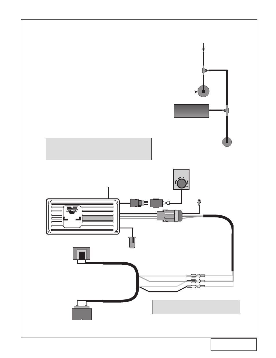
A. The Ignition/Boost Control unit has been prewired
for installation convenience. Installation is a simple
matter of disconnecting the stock connector at
the ignition coil and plugging in the new adapter.
Then plug the stock connector into the adapter.
B. The next step is to provide a good ground for
the black wire and mounting the box in as cool a
place as possible under the hood. The box should
be mounted with the aluminum cover on the bot-
tom.
C. Using the supplied 5/32" hose and 5/32" TEE,
connect the vent on the control unit to the bypass
valve vacuum pressure hose. (See Fig. 17-a.)
D. Route the Ignition/Boost Control wires through the
firewall from the interior side. Mount the knob in
an easily accessible place.
E. Connect the wires to the plastic oval wiring con-
nector on the Ignition/Boost Control unit using the
Snap-on connector supplied in the Ignition/Boost
Control kit.
NOTE: The wiring to the Boost/Control knob can be
matched to either of the corresponding wires in
the boost retard connector.
17. IGNITION/BOOST CONTROL INSTALLATION (High-Output and Cobra Systems Only)
Fig. 17-b
Fig. 17-a
BOOS
T
RET
ARD
0
1
2
3
SUPERCHARGERS
Ignition/Boost
Control
MANUFACTURED FOR
VORTECH SUPERCHARGERS
BY
MSD
®
BLACK
WHITE
RED
ORANGE
BLACK
WHITE
RED
ORANGE
IGNITION
COIL
FROM FACTORY COIL HARNESS
MAGNETIC PICKUP
CONNECTOR (NOT USED)
BOOST
RETARD
CONNECTOR
GROUND
TO MANIFOLD
VACUUM
NOTE:
Wiring diagram for MSD Retard Unit
ONLY.
IGNITION
BOOST
RETARD
BYPASS VALVE
FMU
MANIFOLD
VACUUM